3. Mount the pod onto the personality adapter as shown in the figure below. Do not use force since the pod only fits one way into the personality adapter.
1. Before connecting the ICE200 to the target application, make sure that the ICE200 and the target application are not powered. Of course this also applies when the ICE200 is removed from the target. When connecting or disconnecting the ICE200 from the host PC, make sure that both are not powered.
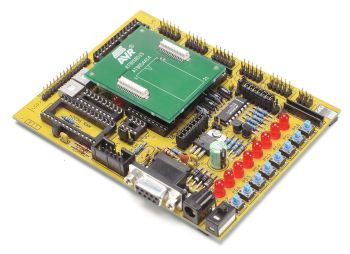
2. Start inserting a personality adapter (see figure below). Make sure that the pin 1 on the personality adapter correspond with the pin 1 on the target socket.
3. Mount the pod onto the personality adapter as shown in the figure
below. Do not use force since the pod only fits one way into the personality
adapter.

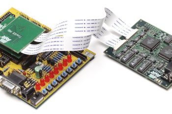
4. If the flexible printed circuit (FPC) is not already connected to the pod and the main board, connect it as shown in the figure below. Note that the FPC lead points must face up, away from the PCB.
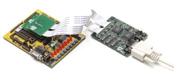
5. Check that the host PC is off and connect the ICE200 to the host. Use the 9-pin RS232C cable that is accompanying the ICE200. Connect the male cable connector to the ICE200 and the female cable connector to the host. Note that the ICE200 does not support hot-swapping i.e. never connect the ICE200 to a powered host.
6. The host PC can now be powered and the AVR Studio can then be started. However, do not open any files before connecting power supply to the ICE200. If the ICE200 is not powered then AVR Studio cannot detect the emulator and therefore enters simulation mode.
7. The ICE200 has no power switch. Just connect the power supply cable shipped with the ICE200 to a +9V to +15V DC power supply, and then connect the power cable to the ICE200 (see the figure below). A battery eliminator is a good alternative to the laboratory power supply shown on the figure.
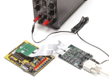
8. Enable the target power supply. The red LED will now be lit, telling that power is present, but no connection to the host PC has been established.
The hardware is now ready for use. Use the checklist below to ensure that the setup was done correctly, and then proceed to the next section: ICE200 Configuration.
Checklist
1. All units are powered off before connecting them.
2. Personality adapter inserted.
3. Pins on adapter corresponds with pins on target.
4. Pod mounted.
5. FPC mounted.
6. RS232 cable connected.
7. Host turned on.
8. Target and ICE200 connected to power supplies.
See Also