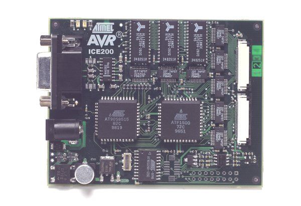
The main board contains the program memory (overlay memory) which holds the application code that is being emulated. The main board also contains logic for communicating with the host PC, and the breakpoint logic. The level converters allows the target to operate at a different supply voltage than the emulator. The level converters also protects the emulator and the target from being damaged if only one of them are powered. Due to this feature, a strict power up sequence is not required.
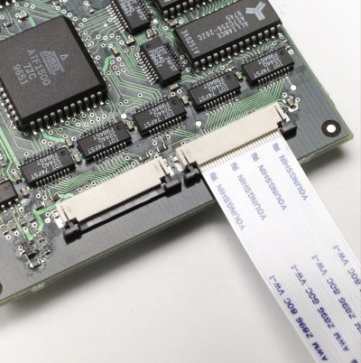
The FPC or Flexible Printed Circuit connects the main board to the ICE200
pod. The actual appearance of the FPC might differ from the figure.
| WARNING!
The FPC connectors on both the main board and the pod have limited durability. Do NOT disassemble the FPC from the main board or the pod. |
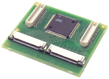
The pod contains the AT90EM04 emulator chip. This chip contains nine
different AVR devices and some special emulation resources. Due to the
fact that the AT90EM04 is located on the pod close to the target, the electrical
characteristics are nearly identical to the actual chip being emulated. Note
that the AT90EM04 must be supplied with power and a clock source (i.e. a
crystal, resonator, oscillator or any other clock generator) from the target.
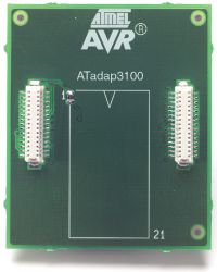
The personality adapters map the pin-out from AT90EM04
to each micro-controller it supports. The adapters include
an identification code that AVR Studio uses for automatic
device type detection. The ICE200 kit contains five
different personality adapters for dual inline package (DIP)
devices. The personality adapter shown below is for the AT90S8535.
See Also