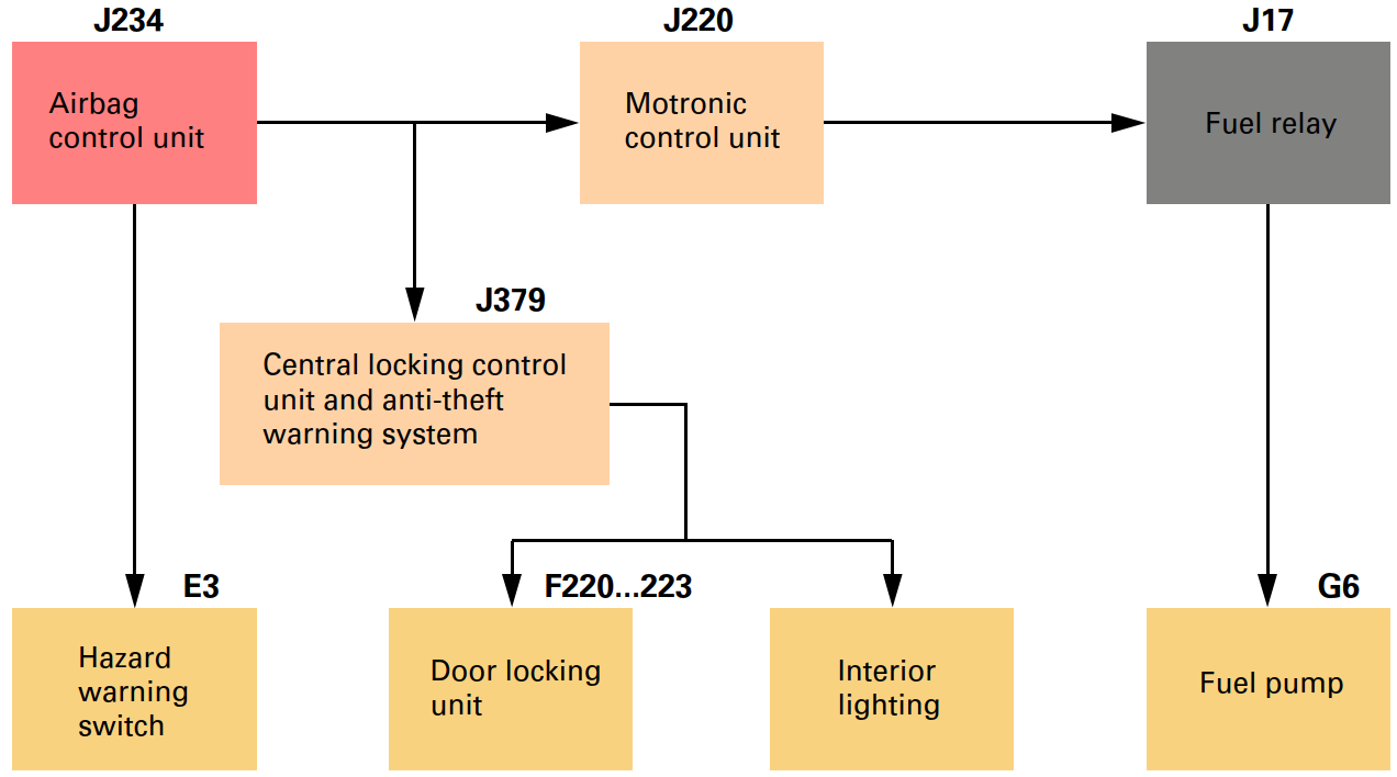
Fuel cut-off
The fuel tank is made of plastic and is housed in a protected position in front of the rear axle.
The central locking control unit receives this signal simultaneously and unlocks the vehicle doors.
The hazard warning lights are activated automatically and the interior
lighting is switched on.
A restart function enables the engine to be
restarted after an accident and it can be moved from the danger zone under its
own power.
The Audi TT Coupé is the first Audi to be equipped with a fuel cut-off.
In
connection with an airbag trigger mechanism (crash signal output), the Motronic
control unit switches the fuel pump off.
Drive units TURBO
Charging
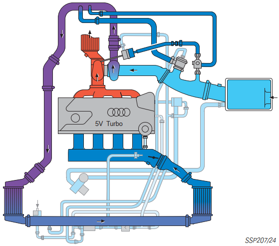
The turbocharging system comprises the following
components:
– Exhaust emission turbocharger
– Charge air cooler
– Charge pressure control
– Air divert control in overrun
The flow energy of the exhaust
emissions is transferred to the fresh air entering the exhaust gas turbocharger.
In the process, the air required for combustion is compressed and the volume of
air entering the cylinders per working cycle is thus increased.
The air temperature, increased
by compression, is again reduced in the charge air cooler. Since the density of
the cooled air is higher, the amount of fuel-air mixture entering the engine is
greater, too.
The result is an increase in power output for the
same displacement and engine speed.
In the case of the 1.8-ltr. 5V
turbocharged engine, turbocharging is also used to provide high torque from the
bottom end to the top end of the rev band.
Charge pressure increases in
proportion to the turbocharger speed. The charge pressure is limited to prolong
the life of the engine. The charge pressure control performs this task.
The air divert control
prevents the turbocharger slowing down unnecessarily if the throttle valve loses
suddenly.
Charge pressure control
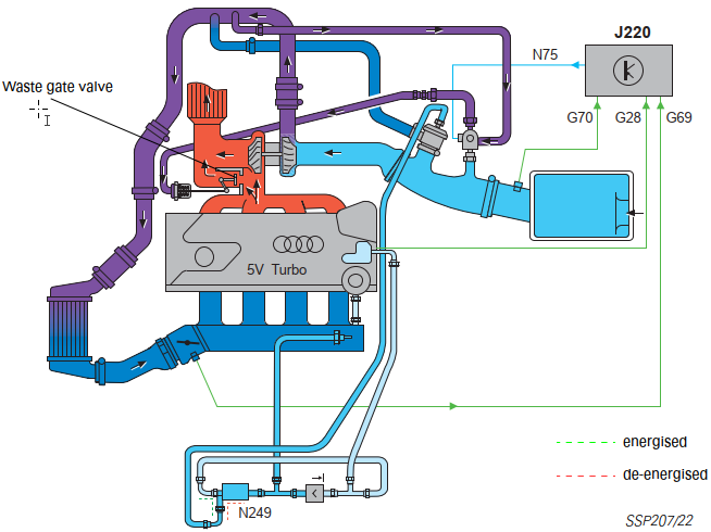
The engine control unit calculates the charge pressure setpoint from the
engine torque request.
The engine control unit regulates the charge
pressure as a function of the opening time of the solenoid valves for charge
pressure limitation N75. For this purpose, a control pressure is generated from
the charge pressure in the compressor housing and the atmospheric pressure.
This control pressure counteracts the spring pressure in the charge pressure
control valve (vacuum box) and opens or closes the waste gate valve in the
turbocharger.
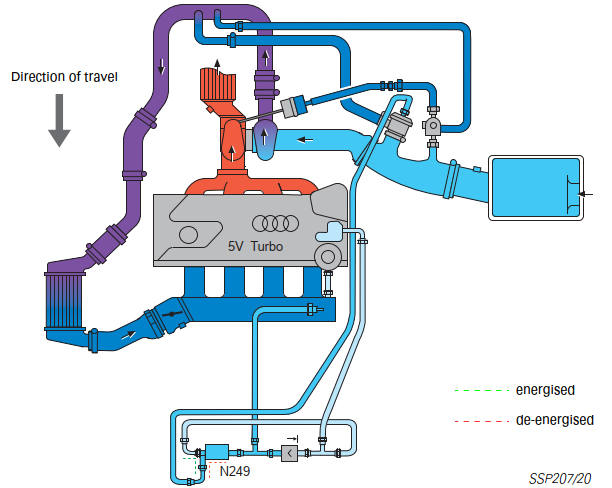
In the de-energised state, the solenoid valve N75 is closed
and the charge pressure acts directly on the vacuum box. The charge pressure
control valve opens at low charge pressure.
If the control fails, the maximum charge pressure is limited to a basic
charge pressure (mechanical charge pressure).
If the bypass is closed,
the charge pressure rises.
In the lower engine speed range, the turbocharger
supplies the charge pressure required to develop high torque or the required
volume of air.
As soon as the charge pressure has reached the calculated
charge pressure, the bypass opens and a certain quantity of exhaust gas is
ducted past the turbine. The turbocharger motor speed
decreases, and so too
does the charge pressure.
For more detailed information regarding charge
pressure control, please refer to SSP 198.
The engine control unit
calculates the charge pressure setpoint from the engine torque request.
The engine control unit regulates the charge pressure as a function of the
opening time of the solenoid valves for charge pressure limitation N75. For this
purpose, a control pressure is generated from the charge pressure in the
compressor housing and the atmospheric pressure.
This control pressure
counteracts the spring pressure in the charge pressure control valve (vacuum
box) and opens or closes the waste gate valve in the turbocharger.
In the
de-energised state, the solenoid valve N75 is closed and the charge pressure
acts directly
Air divert control in overrun
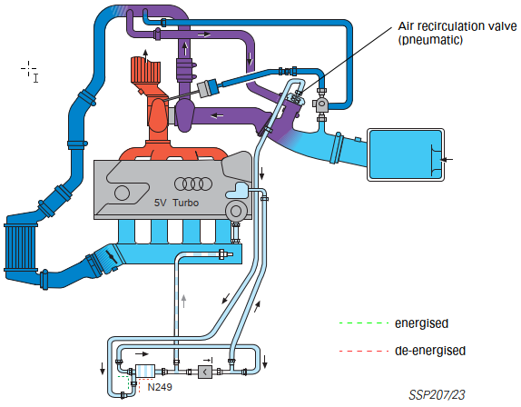
When the throttle valve is closed, it produces a
backpressure in the compressor circuit due to the charge pressure still present.
This causes the compressor wheel to decelerate rapidly. When the throttle valve
is opened, the speed of the turbocharger must again be increased. The air divert
control in overrun prevents turbo lag, which would otherwise occur.
The
air recirculation valve is a mechanically activated and pneumatically controlled
spring diaphragm valve. It is also activated via an electrically activated air
recirculation valve for turbocharger N249. This, in connection with the vacuum
reservoir, enables the air recirculation valve N249 to operate independently of
the intake manifold pressure. If the air recirculation valve fails, control
takes place as a result of the engine vacuum downstream of the throttle valve.
As soon as the throttle valve is closed, the air
recirculation valve briefly closes the compressor circuit.
The vacuum counteracts the
spring in the valve. The valve opens, and the compressor and intake sides of the
compressor circuit close for a short period of time. There is no deceleration of
the compressor wheel.
When the throttle valve re-opens, the intake manifold
vacuum drops. The air recirculation valve is closed by the spring force. The
compressor circuit no longer closes briefly. Full charger speed is available
immediately.
For more detailed information regarding the air divert
control in overrun, please refer to SSP 198.
Quick-start sender wheel
The quick-start sender wheel is attached to the camshaft. It supplies a signal which enables the engine control unit to determine the position of the camshaft relative to the crankshaft more quickly and, in combination with the signal which the engine speed sender supplies, to start the engine more quickly.
On previous systems, it was not possible to initiate the first combustion
cycle until a crank angle of approx. 600˚ - 900o was reached. The quick-start
sender wheel enables the engine control unit to recognise the position of the
crankshaft relative to the camshaft after a crank angle of 400˚ - 480o.
This
allows the first combustion cycle to be initiated sooner and the engine to start
more quickly.
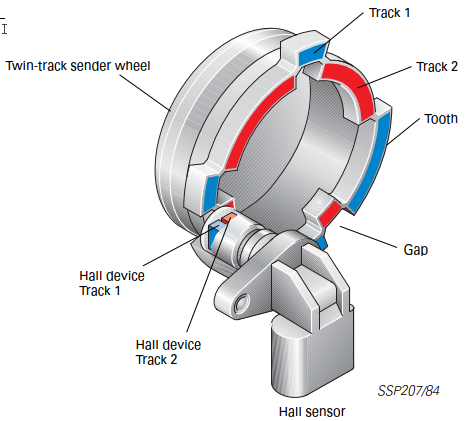
The quick-start sender wheel comprises a twin-track sender wheel and a Hall sensor. The sender wheel is designed so that two tracks are located side by side. In the position where there is a gap in one track, there is a tooth in the other track.
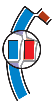
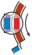
The control unit compares the phase sensor signal with the reference mark
signal and thus ascertains the working cycle currently taking place in the
cylinder.
Low phase signal = Compression cycle
High phase signal = Exhaust cycle
The signal which the engine speed sender G28 supplies enables the injection cycle to be initiated after a crank angle of approx. 440o.
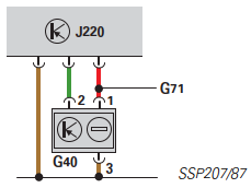
Electrical circuit
The Hall sender G40 is connected to the sensor
earth terminal of the engine control unit.
The signal which the engine
speed sender G28 supplies enables the injection cycle to be initiated after a
crank angle of approx. 440o.
Even if the Hall sender fails, it is still
possible to start the engine.
Charging 165 kW
To increase the power output and torque of the 1.8-ltr. 5V engine to 165 kW,
it was necessary to make various design modifications to the basic engine of the
Audi TT Coupé developing 132 kW.
A characteristic feature of the engine
is its higher air demand, making it necessary to enlarge the diameter of the
intake port and exhaust gas turbocharger.
Since the previous charge air cooler was no longer capable of effectively cooling down the increased air flow through the exhaust gas turbocharger, it was necessary to accommodate a second, parallel charge air cooler on the left-hand side of the vehicle.
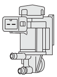
Secondary air injection valve N112
The secondary air injection valve is an electropneumatic valve. It is switched
by the Motronic control unit and controls the combi-valve.
To open the
combi-valve, the secondary air injection valve releases the intake manifold
vacuum.
To close the combi-valve, the secondary air injection valve releases
atmospheric pressure.
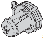
Secondary air pump V101
The secondary air
pump relay J299 which the Motronic control unit drives switches the electric
current for the secondary air pump motor V101. The fresh air which is mixed with
the
exhaust gases is drawn out of the air filter housing by the secondary air
pump and released by the combi-valve.
This valve also prevents hot
exhaust gases entering and damaging the secondary air pump.
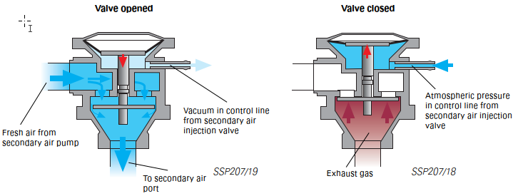
The combi-valve
The combi-valve is bolted to the secondary air duct of
the cylinder head.
The air path from the secondary air pump to the secondary
duct of the cylinder head is opened by the vacuum from the secondary air
injection valve.
The combi-valve
The combi-valve is bolted to the secondary air duct of
the cylinder head.
The air path from the secondary air pump to the secondary
duct of the cylinder head is opened by the vacuum from the secondary air
injection valve.