Volkswagen 01M Transmission. Manual - part 37
 

  Index      Volkswagen     Volkswagen 01M Transmission - service manual 2001 year


Search              


Content   ..  35  36  37  38   ..


Volkswagen 01M Transmission. Manual - part 37


7

Technical Service Information

ELECTRONIC COMPONENTS

Input Speed Sensor (G182)
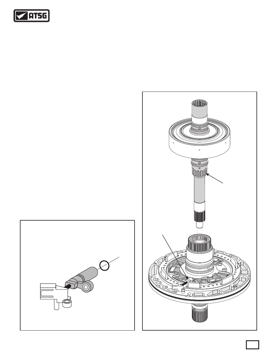
   The Input Speed Sensor (G182) is located in the 
transmission oil pump stator, as shown in Figure 7, 
and retained with a bolt.   The ISS has a Yellow 
connector that mounts on the back side of the oil pump 
body and is also retained with a bolt, as shown in 
Figure 7. The ISS signal is routed through the 8-way 
case connector. 
   The ISS is triggered by rotor teeth on the turbine 
shaft to determine exact transaxle turbine speed, as 
shown in Figure 7.   The TCM uses this information to 
control line pressure for garage shifts, control and 
monitor torque converter lock-up clutch, monitor 
gear ratios and diagnosis of shift components via the 
Dynamic Shift Program (DSP), which is VW's name 
for the shift adapt feature in the TCM.
   The ISS is based on the Hall Effect principle.  The 
signal is a square-wave signal whose frequency is 
proportional to turbine shaft speed.   Should the Input 
Speed Sensor fail, the engine RPM sensor is used as a 
back-up, but when engine RPM sensor is used there 
will be no shift adapt operations, no controlled pulse 
width modulation for   TCC lock-up (apply and 
release only) and no pressure control on garage shifts 
(N-D, N-R) which will create harsh garage shift 
engagements.
   The Input Speed Sensor is shown in Figure 6.

INPUT SPEED SENSOR (G182)

5.0M Ohms Resistance

at room temperature

ISS (G182)

Location

ISS (G182)

Rotor Teeth

3 U

Figure 6

Figure 7

Special Note:
   The ISS and OSS are Hall Effect Sensors and 
should be checked using a scope under operating 
conditions.   The resistance values provided in the 
Figures below are from new sensors.   Resistance 
checks on these type of sensors would, at best, 
inform you of either open or grounded circuits 
within the sensor itself.

50 50

63 63

142

7

A

T

Output Speed Sensor (G195)
   The Output Speed Sensor (G195) is located in the 
transmission case below the valve body, as shown in 
Figure 9, and retained with a bolt.   The OSS has a 
White connector that mounts on one of the solenoid 
pin retaining brackets on the valve body. The OSS 
signal is fed through the 8-way case connector.
   The OSS is triggered by the external lugs on the rear 
planetary ring gear,  to determine exact transmission 
output shaft speed.   The TCM uses this information to 
determine shift points, control and monitor torque 
converter lock-up clutch, monitor gear ratios and 
diagnosis of shift components via the Dynamic Shift 
Program (DSP), which is VW's name for the shift 
adapt feature in the TCM.
   The OSS is based on the Hall Effect principle.  The 
signal is a square-wave signal whose frequency is 
proportional to output shaft speed.   Should the Output 
Speed Sensor fail, the speed signal from the ABS 
Control Module is used as back-up, with limited shift 
adapt capability. 
   The Output Speed Sensor is shown in Figure 8.

Special Note:
   The ISS and OSS are Hall Effect Sensors and 
should be checked using a scope under operating 
conditions.   The resistance values provided in the 
Figures below are from new sensors.   Resistance 
checks on these type of sensors would, at best, 
inform you of either open or grounded circuits 
within the sensor itself.

OUTPUT SPEED SENSOR (G195)

5.0M Ohms Resistance

at room temperature

Figure 8

Figure 9

8

Technical Service Information

 31  OUTPUT SPEED SENSOR AND CONNECTOR ASSEMBLY.
 32  OSS AND RETAINER BOLTS, 11.5 MM (0.452") LONG (2 REQ).
 33  OUTPUT SPEED SENSOR HARNESS RETAINER.

31

32

32

33

9

Technical Service Information

Pressure Switch 2

Location (G194)

Pressure Switch 1

Location (G193)

Temp Sensor

Location (G93)

(Some Models Only)

(Some Models Only)

ELECTRONIC COMPONENTS (CONT'D)

Pressure Switches 1 (G193) And 2 (G194)
   Some "09D" transmissions are equipped with two 
pressure switches that screw into the valve body 
casting in the locations shown in Figure 10.   Both 
switches are "normally open" switches that connect to 
ground when pressure exceeds approx. 44 psi and are 
used to verify valve movement in the valve body 
assembly.
   Pressure Switch 1 (G193) is used to verify activation 
of the K-1 clutch.
   Pressure Switch 2 (G194) is used to verify activation 
of the B-2 clutch.   Therefore, pressure switch 2 is 
closed in tiptronic mode only, 1st gear. The only other 
time the B-2 clutch is required is in reverse (R) gear.  
Pressure Switch 2 does not close in the reverse 
position, as reverse is engaged by the manual valve 
hydraulically.
  Note: Pressure switches are used only on some
   models equipped with the "09D" transmission.

TRANSAXLE FLUID TEMP SENSOR (G93)

Temperature F° (C°)

-22°F (-30°C)

50°F (10°C)

77°F (25°C)

230°F (110°C)

293°F (145°C)

Resistance

37K - 51K Ohms

5K - 8K Ohms

3K - 5K Ohms

230 - 265 Ohms

100 - 120 Ohms

"O" RING

FLUID TEMP

SENSOR

A-3

2

2

2

2

AIS

IN

AIS

IN

AIS

IN

AIS

IN

8 8

6 0

8 8

6 0

8 8

6 0

8 8

6 0

1

1

1

1

9A

N3K01

75

5

9AN3K0

17

62

8BA

3K01631

9A

N3K01

748

9AN3K0

1742

4AM3K03O1

8

PRESSURE SWITCH AND TEMP SENSOR LOCATIONS

12.0 MM (0.472")

LENGTH

Figure 10

Figure 11

Continued on Page 10

10

Technical Service Information

ELECTRONIC COMPONENTS (CONT'D)

Transaxle Fluid Temp Sensor (G93)
   The Transaxle Fluid Temp Sensor (G93) is located in 
the valve body and is mounted with a retaining plate, 
as shown in Figure 10.   Notice in Figure 11 that an "O" 
ring is required, as it is mounted into an oil passage.   
The TFT is an integral part of the 8-way case 
connector and wire harness assembly.
   The TFT is a negative temperature coefficient 
sensor, which means that as temperature rises the 
resistance decreases, as shown in Figure 11.
   Starting at 150°C (270°F), the converter clutch is 
applied more frequently.  If this does not result in 
cooling of the ATF, reduction of engine torque is 
initiated at 170°C (306°F).
   Should the TFT fail, a substitute value is generated 
from the engine temperature and operating duration.   
There will be no controlled operation (ramping) of the 
converter clutch (ON or Off only) and no controlled 
shift adapt pressures, which usually results in harsh 
engagements. 

Solenoid Identification And Location
   The 09D transmission uses a total of 8 different 
solenoids located in the valve body that are used to 
apply or release the clutches, control the main line 
pressure and apply or release the torque converter 
clutch.   They are identified and their locations are 
shown in Figure 12. 
   There are three different types of solenoids used in 
the "09D" transmission.   There are two "Normally 
Closed" On/Off solenoids, one "Normally Vented" 
Pulse Width Modulated (PWM) solenoid, and the 
other five are "Normally Applied" Pulse Width 
Modulated (PWM) solenoids.   
   Refer to Figure 13 for their individual functions and 
Figure 12 for their locations in the valve body.

A-3

2

2

2

2

AISIN

AISIN

AIS

IN

AIS

IN

8 8

6 0

8 8

6 0

8 8

6 0

8 8

6 0

1

1

1

1

9AN3K01755

9AN3K

01762

8BA3

K01

63

1

9AN3K01748

9AN3K

017

42

4AM3K03O18

SOLENOID IDENTIFICATION AND LOCATIONS

N88 Solenoid

(On-Off)

N91 Solenoid

(TCC)

N282 Solenoid

(K2 Clutch)

N283 Solenoid

(B1 Clutch)

N93 Solenoid

(Line Pres)

N90 Solenoid

(K3 Clutch)

N92 Solenoid

(K1 Clutch)

N89 Solenoid

(On-Off)

Figure 12


Content   ..  35  36  37  38   ..