Volkswagen 01M Transmission. Manual - part 40
 

  Index      Volkswagen     Volkswagen 01M Transmission - service manual 2001 year


Search              


Content   ..  38  39  40  41   ..


Volkswagen 01M Transmission. Manual - part 40


19

Technical Service Information

A-3

2

2

2

2

AISIN

AISIN

AISIN

AISIN

8 8

6 0

8 8

6 0

8 8

6 0

8 8

6 0

1

1

1

1

9A

N3K

01755

9A

N3

K0

1762

8B

A3K

016

31

9A

N3K

01748

9A

N3K

017

42

4A

M

3K

03O

18

142

7

AT

JP

  57344-0

1

09D 321 361

>F

e/Zn

<

24

15

84

54

0

TR

A0

10

Transaxle

(Multifunction F125)

Range Switch

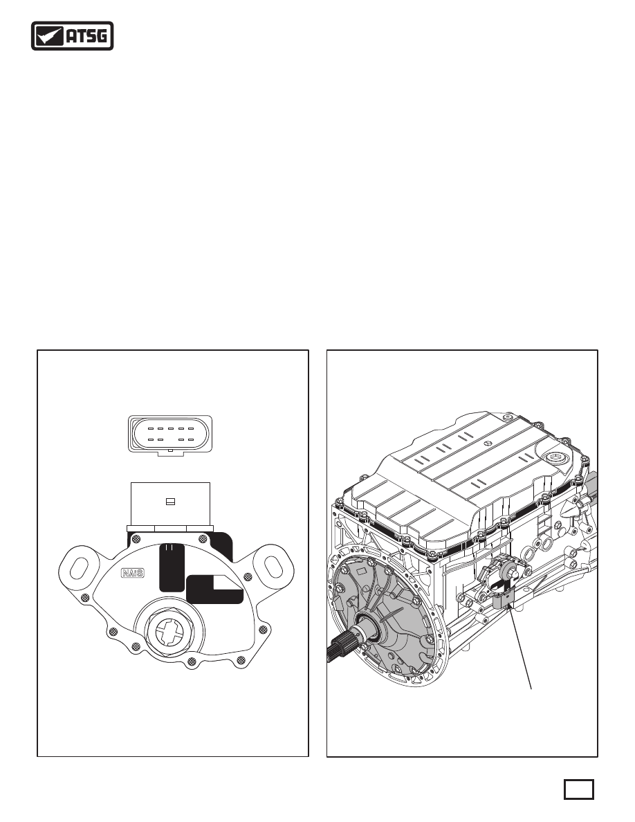
Figure 23

Figure 22

TRANSMISSION RANGE SWITCH LOCATION

TRANSMISSION RANGE SWITCH

(MULTIFUNCTION SWITCH F125)

ELECTRONIC COMPONENTS (CONT'D)

Transmission Range Switch (Mulitfunction F125)

Diagnosis

Diagnosis (Cont'd)

   The Transmission Range Switch (TRS) is located on 
the right hand side of the transmission, as shown in 
Figure 23.   The TRS is a mechanical multi-position 
switch with 6 sliding contacts, four selector position 
switches, one reverse switch and one switch for 
positions P/N, for starting control. 
   The TRS is shown in Figure 22 and if removed or 
replaced, a position to the selector (manual) shaft 
must be set using special tool from Volkswagen.

   The only ignition voltage sent to the switch goes in at 
terminal 10 and goes through only the reverse switch, 
as shown in Figure 24.   Voltage exits through terminal 
8 and is sent to the reverse lamps and the TCM.  
Diagnosis here is easily done using a volt meter. 

   The remainder of the switches provide a ground 
signal for the starter relay through the P/N switch and 
ground signal to the TCM through the position 
switches, as shown in Figure 24.         These switches 
must be checked with the DVOM set to Ohms. Notice 
in Figure 24 that terminals 3 and 4 provide the ground 
into the switches.   Use the Ohm meter across 
terminals 4 and 2 to check for the Park and Neutral 
positions, as shown in the chart provided in Figure 24.   
With the Ohm meter on terminal 3, you should have 
continuity across the terminals shown in the chart in 
Figure 24, related to the position of the gear selector 
lever.

2415

84540

TRA010

1

2

3

4

5

6

7

8

9

10

Figure 24

1001

1101

0101

0110

1111

1101

1101

0111

0111

Switch

Position

Transition

Position

2

4

10

8

3

1

7

9

5

Lever

P/N Signal

Rev Signal

Position Signal

Data Block 9.4 Value

P

R

N

D

S

Black/Green

Black/Green

Black/Green

Bl

ack/

Gree

n

Bl

ac

k/

Gre

en

Bl

ack/

Gree

n

Gray/Black

White/Black

Gray/Black

Yellow

Yellow

Y

el

low

Yellow

Brown

Yellow/Blue

Violet/Black

Red/Yellow

Brown

NOT USED

GROUND TO

STARTER RELAY

TO REVERSE LAMPS

TO SHIFT LEVER ASSEMBLY

TERMINAL 7 (SEE WIRE SCHEM.)

HOT IN

RUN/START

P/N

SWITCH

REVERSE

SWITCH

POSITION

SWITCHES

6

5

3

2

1

8

7

10

9

4

Transmission

Range

Switch

Wire Colors

May Vary

TCM

TCM

22

47

21

10

36

REV SIG

POS SIG

POS SIG

POS SIG

POS SIG

}

FUSE

7

(10A)

TRANSmission RANGE SWITCH SCHEMATIC

1

2

3

4

5

6

7

8

9

10

Face View Looking

Into TRS Connector

20

Technical Service Information

-

+

         When the "Park" position is selected, there is no 
powerflow through the transmission.   The parking 
pawl is engaged which locks the output shaft to the 
case.   The engine can be started and the ignition key 
can be removed.

P

         When the "Neutral" position is selected, there is no 
powerflow through the transmission.   The output 
shaft is not held and is free to rotate and the engine can 
be started.   This position can also be selected while 
the vehicle is moving, to restart the engine if that 
becomes necessary.

N

         When the "Reverse" position is selected, the 
vehicle can be operated in a rearward direction at a 
reduced gear ratio.

R

           When the "Sport" position is selected, the lock 
button must be pressed to shift into "S", the TCM will 
select gears automatically using a performance 
oriented shifting program.
   When the shift lever in the "S" position and moved 
into the right hand selector gate, it enables the driver 
to select the range of gears by tapping the selector 
lever towards the "-" or "+" to cause the transaxle to 
downshift or upshift. 

S

S - Cont'd

         The "Drive" position is the normal position for 
most forward gear operations.   The Drive position 
provides automatic upshifts and downshifts, apply 
and release of the converter clutch, and maximum fuel 
economy during normal operation. Drive range 
allows the transmission to operate in each of the six 
forward gear ratios.   Downshifts are available for safe 
passing, by depressing the accelerator.
 The "Tiptronic" in the Touareg is available in the 
selector lever as well as the steering wheel, by moving 
the selector lever to the right out of the "D" position.

D

SHIFT QUADRANTS

TYPICAL SHIFT QUADRANT

Selector Lever

Steering Wheel Paddles

Selector Lever Positions

   The appearance of the selector lever, as shown in 
Figure 25, will vary between the different vehicle 
applications.   However, the operation and function 
remains the same with the use of the TR-60SN.

   Steering wheel paddles are available as options,as 
shown in Figure 25, and they also will vary in 
appearance with the different vehicle applications.  
However, operation and function remains the same 
with the TR-60SN.

Lock Button

Thumb Paddles

Upshift

Paddle

Downshift

Paddle

   On models equipped with the steering wheel 
paddles, the paddles are used to upshift and downshift 
the transmission manually, instead of the shift lever.

Figure 25

P

R

+

N
D

S

21

Technical Service Information

When towing, the ATF pump is not operated, and 
therefore rotating components are not lubricated.   To 
avoid severe damage to the transaxle, the following   
conditions must be met:
       - The selector lever must be in the “N” Neutral 
       position.
       - Towing speed must not exceed 31 mph 
      (50km/h). 
       -   Vehicle must not be towed further than 31 miles
      (50 km).

       - Automatic upshifts when the maximum RPM is
      reached.
       - Automatic downshifts when the RPM falls
      below the programed minimum RPM.
       - Kickdown shifting available.
       - Acceleration from standing start in second gear
      by selecting 2nd before accelerating.
       - Upshift or downshift prevention.

40

50

60

60

40

20

0

70

50

30

10

90

50

130

0

1/2

1/1

P

TIPTRONIC UPSHIFT AND DOWNSHIFT

Steering Wheel Paddles

Tiptronic Shifting Strategy

Emergency "Limp" Mode

Towing Restrictions

LED Display On Instrument Panel

   Steering wheel paddles are available as options,as 
shown in Figure 25, and they also will vary in 
appearance with the different vehicle applications.  
However, operation and function remains the same 
with the TF-60SN.  These operational paddles are 
found in the steering wheel on the left and right hand 
side, as shown in Figure 25.
   Upshifts and downshifts occur by tapping the 
appropriate paddle.   The shift signals are an input to 
the TCM, which in turn carries out the request.
   If the Tiptronic paddles in the steering wheel are 
operated while in automatic mode, the TCM enters 
"Tiptronic Mode".  If the paddles are not operated, the 
TCM returns to the automatic mode after a 
preprogramed amount of time.
   In case of a signal failure, no Tiptronic functions are 
possible using the steering wheel paddles.

   These vehicles are also equipped with an LED 
display on the instrument panel that will display the 
gear selected with the selector lever, as shown in 
Figure 26. 
   When the vehicle is first started, the display will be 
"P", as shown in Figure 26.   If reverse is selected the 
"R" will be displayed.
   When Drive is selected for the automatic forward 
mode the "D" will be displayed momentarily and will 
then go to "1", as you are still in first gear.  As you are 
driving, the gear that the transaxle is in will be 
displayed on the instrument panel.
   When in the Tiptronic Mode, the gear selected by 
pressing the paddles will be displayed in the 
instrument panel.   Keep in mind that 2nd gear starts 
can be achieved using this feature.   3rd gear standing 
starts are not allowed.

Figure 26

In mechanical emergency running mode, 3rd gear is 
always engaged.   If the transmission is already in 4th, 
5th or 6th gear, the current gear is maintained until the 
selector lever is placed into the neutral position and 
the engine is stopped. 
   When starting off, 3rd gear is always engaged 
whether the selector lever is in the D or S position. 
Reverse is available. 
   System pressure is controlled to the maximum value; 
the shifting elements are pressurized to maximum 
shifting pressure. This results in a hard shift when 
engaging the driving mode.   The torque converter 
lock-up clutch remains off.

22

Technical Service Information


Content   ..  38  39  40  41   ..