Volkswagen 01M Transmission. Manual - part 49

55
Technical Service Information
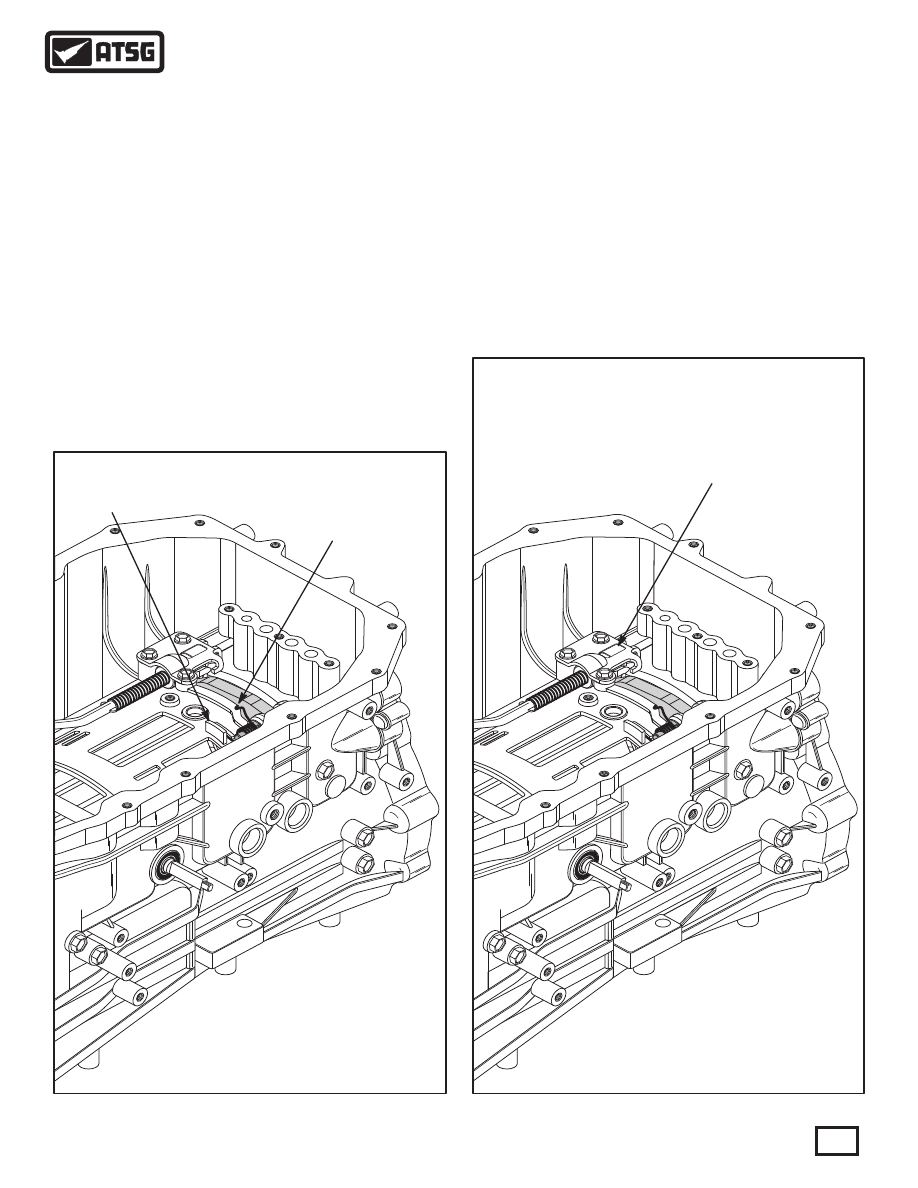
Figure 84
Figure 85
TRANSMISSION CASE ASSEMBLY (CONT'D)
COMPONENT REBUILD (CONT'D)
13. Rotate parking pawl down into position, against
spring tension, and install inside detent lever and
the park rod and actuator, as shown in Figure 83.
Note: Park rod must be on the top side of the
parking pawl.
14. Lube with a small amount of Trans-Jel® and
install the manual shaft through the case bore
and inside detent lever, as shown in Figure 83.
15. Align and install the rolled pin through inside
detent lever and the manual shaft, as shown in
Figure 83.
16. Install the park rod guide on top of the park rod,
as shown in Figure 83, and torque the three bolts
to 28 N·m (20 ft.lb.).
17. After installation, the return spring must be on
back side of the case tab and underneath the
parking pawl, as shown in Figure 84.
18. After installation, park rod must be underneath
the park rod guide and on top of parking pawl,
as shown in Figure 85.
Continued on Page 56
CASE TAB
CASE TAB
RETURN SPRING MUST
BE ON BACK SIDE OF
CASE TAB AND UNDER
PARKING PAWL
RETURN SPRING MUST
BE ON BACK SIDE OF
CASE TAB AND UNDER
PARKING PAWL
PARK ROD MUST
BE UNDERNEATH
GUIDE AND ON TOP
OF PARKING PAWL
PARK ROD MUST
BE UNDERNEATH
GUIDE AND ON TOP
OF PARKING PAWL