Volkswagen 01M Transmission. Manual - part 50
 

  Index      Volkswagen     Volkswagen 01M Transmission - service manual 2001 year


Search              


Content   ..  48  49  50  51   ..


Volkswagen 01M Transmission. Manual - part 50


 501  K2 CLUTCH HOUSING ASSEMBLY.
 504  K2 CLUTCH APPLY PISTON AND "O" RING SEAL ASSEMBLY.
 507  K2 CLUTCH BALANCE PISTON AND RETURN SPRING ASSEMBLY.
 508  K2 CLUTCH BALANCE PISTON RETAINING SNAP RING.

501

504

507

508

501

59

Technical Service Information

Figure 93

Figure 94

K2 CLUTCH HOUSING (CONT'D)

COMPONENT REBUILD (CONT'D)

     8. Lube the piston seals and the seal surfaces in the
       housing with a small amount of Trans-Jel®.
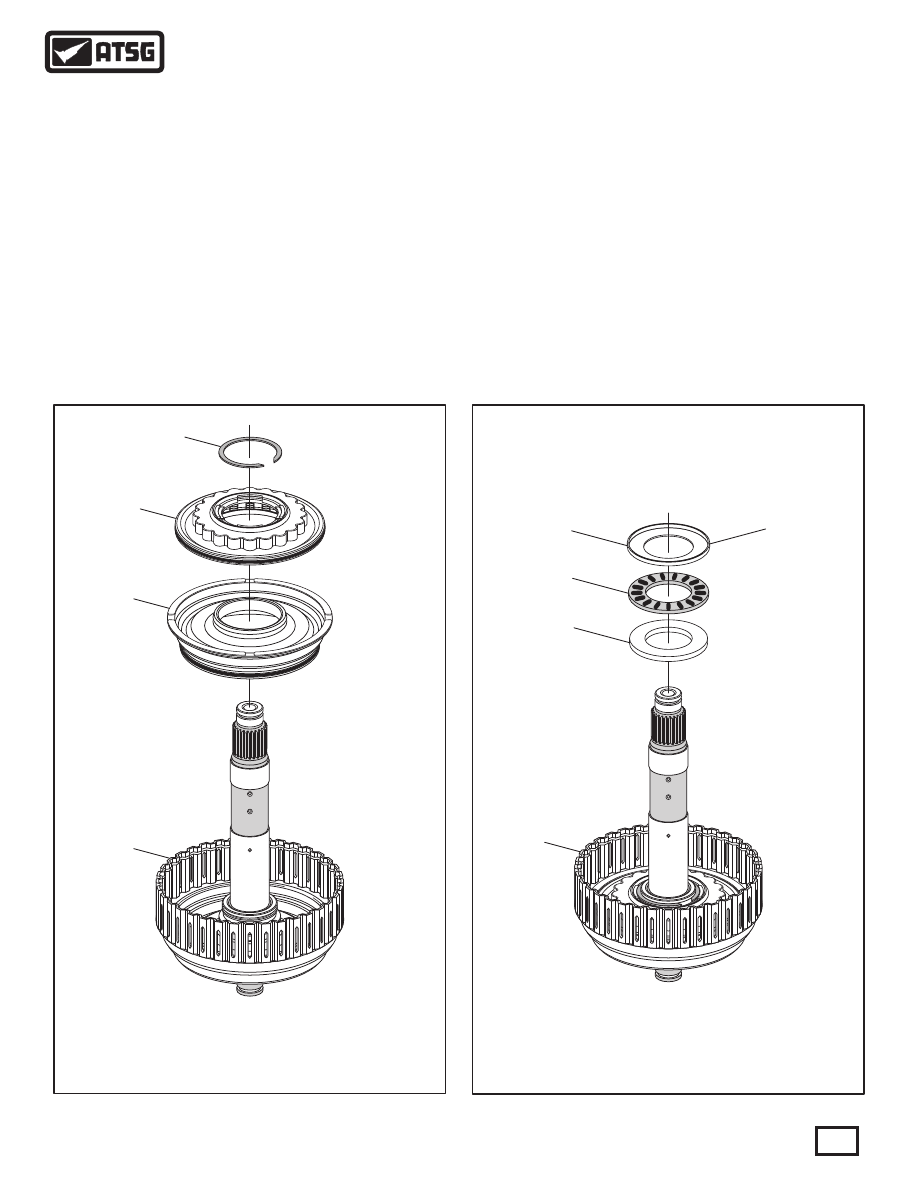
     9. Install the K2 clutch apply piston in K2 clutch
       housing, as shown in Figure 93.
 10. Install the K2 balance piston and return spring
             assembly on top of the apply piston, as shown in
       Figure 93.
 11. Compress balance piston and install snap ring,
       as shown in Figure 93.
       Note: You may have to be innovative with your
             press adapters as this one is more difficult than
       some others because of the shaft.

 12. Install the number 11 thrust bearing rear race 
             and the number 11 thrust bearing, as shown in
       Figure 94, and retain with Trans-Jel®.
       Note: This step can wait until the clutches are
       installed if you wish.
 13. The number 11 thrust bearing front race will be
             installed on the rear planetary carrier during the
       assembly process.

Continued on Page 60

454

454 BEARING RACE

INSTALLS ON REAR

PLANETARY CARRIER

454 BEARING RACE

INSTALLS ON REAR

PLANETARY CARRIER

455

456

 454  NUMBER 11 THRUST BEARING FRONT RACE.
 455  NUMBER 11 THRUST BEARING.
 456  NUMBER 11 THRUST BEARING REAR RACE.
 501  K2 CLUTCH HOUSING ASSEMBLY.

K2 Clutch Clearance Should Be

Approximately .010" Per Friction Plate

501

NO. 11 BEARING

AND BEARING RACE

NO. 11 BEARING

AND BEARING RACE

NO "O" RING

HERE

NO "O" RING

HERE

509

510

511

512

 501  K2 CLUTCH HOUSING ASSEMBLY.
 509  K2 CLUTCH STEEL PLATES   (QUANTITY VARIES).
 510  K2 CLUTCH FRICTION PLATES   (QUANTITY VARIES).
 511  K2 CLUTCH BACKING PLATE, 4.63 MM (.182") THICK.
 512  K2 CLUTCH BACKING PLATE SNAP RING, 2.46 MM (.097") THK.

Figure 95

Figure 96

K2 CLUTCH HOUSING (CONT'D)

COMPONENT REBUILD (CONT'D)

 14. Install the K2 clutch plates beginning with a steel 
             plate and alternating with the friction plates, as 
             shown in Figure 95, until you have the proper
       amount installed as quantity may vary. 
       Note: All friction plates should be soaked in
             proper fluid for 30 minutes before installing.
 15. Install the K2 clutch backing plate, as shown in 
             Figure 95, with the rounded edge toward the
       friction plate  (See Figure 95).
 16. Install the K2 clutch backing plate snap ring, as
       shown in Figure 95.
       Note: There is no "O" ring in the groove of
             the pilot on the K2 clutch housing shaft, as
       shown in Figure 95.
 17. Measure the K2 clutch clearance with a feeler
             gauge between the backing plate and snap ring,
       as shown in Figure 96.
       Note: There are no factory clutch clearance
       specifications available, but the clearances
             were the "traditional" .010" per friction plate
       through-out this unit.
 18. K2 clutch clearance should be approximately 
             .010" per friction plate installed, as shown in
       Figure 96. 

Continued on Page 61

60

Technical Service Information

ROUNDED EDGE

TOWARDS FRICTION

BACKING

PLATE

 458  NUMBER 12 THRUST BEARING FRONT RACE.
 459  NUMBER 12 THRUST BEARING.
 460  NUMBER 12 THRUST BEARING REAR RACE.
 500  K2 CLUTCH HOUSING SEAL RING.
 501  K2 CLUTCH HOUSING ASSEMBLY.

458

459

460

500

501

459 AND 460

WILL BE INSTALLED

IN OUTPUT SHAFT

459 AND 460

WILL BE INSTALLED

IN OUTPUT SHAFT

}

K2 CLUTCH HOUSING (CONT'D)

COMPLETED K2 CLUTCH HOUSING

COMPONENT REBUILD (CONT'D)

 19. Turn the K2 clutch assembly over and install the
       number 12 thrust bearing front race, as shown in
       Figure 97, and retain with Trans-Jel®.
       Note: The number 12 thrust bearing and the 
             rear race will be install in the output shaft.
 20. Set the completed K2 clutch housing aside for 
             the output shaft and rear ring gear component
       assembly process  (See Figure 98).
       Note: There is not an "O" ring that goes in
             the groove on pilot of the K2 clutch housing.

Continued on Page 62

Figure 97

Figure 98

61

Technical Service Information

NO "O" RING

HERE

NO "O" RING

HERE

COMPONENT REBUILD (CONT'D)

COMPONENT REBUILD (CONT'D)

OUTPUT SHAFT/REAR RING GEAR ASSEMBLY

   The output shaft, the rear planetary ring gear and the 
K2 clutch housing are removed as an assembly and 
installed as an assembly.  The K2 clutch housing cannot 
be removed with out seperating the rear planetary ring 
gear from the output shaft, and must be installed during 
the output shaft component rebuild section.   They are 
connected with an internal snap ring in the output shaft 
that locks into an internal groove in the rear planetary 
ring gear. 
   Exploded view of all of these components is shown in 
Figure 99 below.

OUTPUT SHAFT, REAR RING GEAR AND ASSOCIATED PARTS, EXPLODED VIEW

454

455

456

457

501

458

459

460

461

462

464

465

466

463

 454  NUMBER 11 THRUST BEARINNG FRONT RACE.
 455  NUMBER 11 THRUST BEARING.
 456  NUMBER 11 THRUST BEARING REAR RACE.
 457  REAR PL ANETARY RING GEAR.
 458  NUMBER 12 THRUST BEARING FRONT RACE.
 459  NUMBER 12 THRUST BEARING.
 460  NUMBER 12 THRUST BEARING REAR RACE.

 461  OUTPUT SHAFT CAGED NEEDLE BEARING.
 462  OUTPUT SHAFT, 4WD.
 463  REAR PL ANETARY RING GEAR RETAINING SNAP RING.
 464  OUTPUT SHAFT SEAL RING S  (2 REQUIRED).
 465  NUMBER 13 THRUST BEARING.
 466  NUMBER 13 THRUST BEARING RACE.
 501  K2 CLUTCH HOUSING COMPLETE.

Figure 99

     1. Disassemble the output shaft/ring gear assembly 
       using Figure 99 as a guide.
     2. Clean all output shaft/ring gear parts thoroughly 
       and dry with compressed air.
     3. Inspect all output shaft/ring gear parts thoroughly 
             for any wear and/or damage, and replace parts
       as necessary.

CAUTION: At the time of this printing, there are 
not any new "hard parts" available from the 
manufacturer for this unit.   The only source will 
be used aftermarket suppliers.

Continued on Page 63

62

Technical Service Information


Content   ..  48  49  50  51   ..