Volkswagen 01M Transmission. Manual - part 52

COMPLETED F1 SPRAG ASSEMBLY
67
Technical Service Information
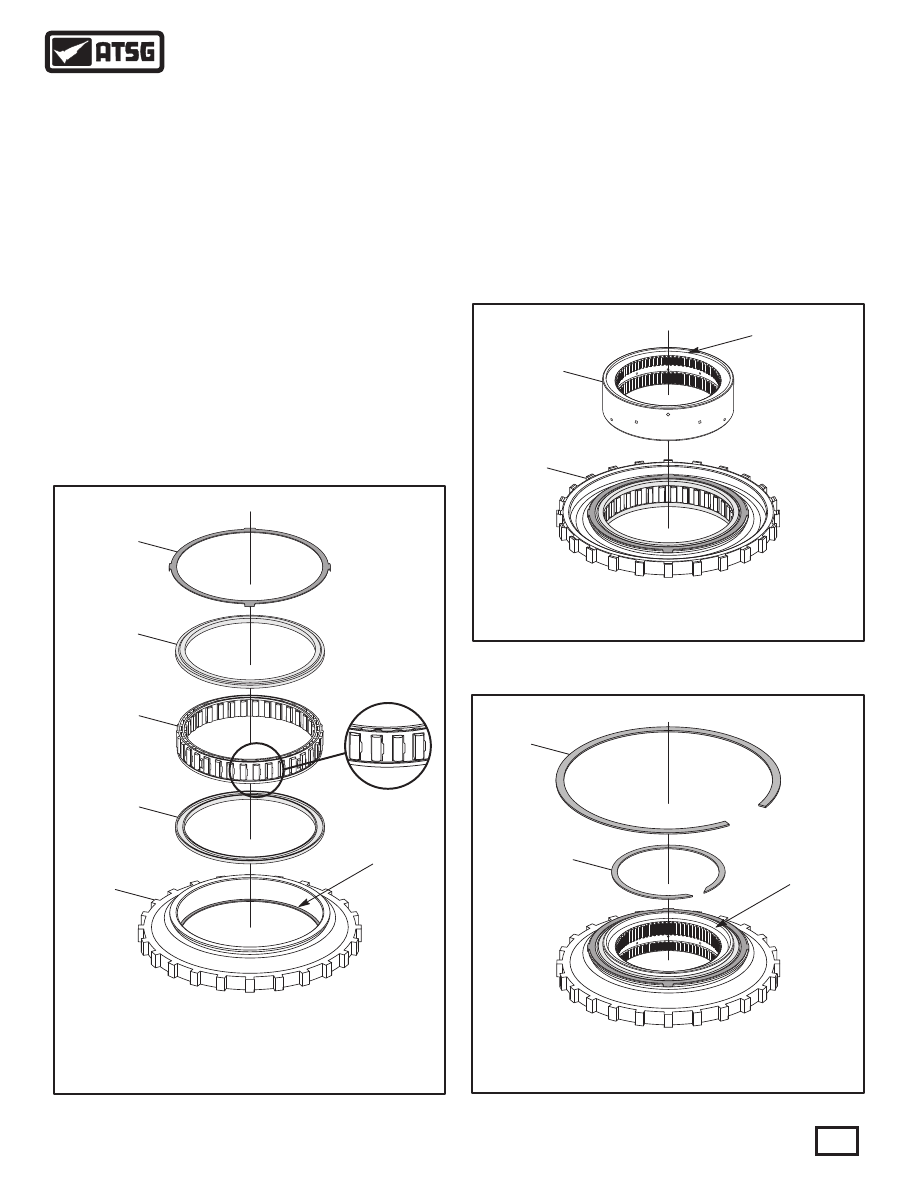
Figure 110
Figure 112
Figure 111
413
413
414
"SQUARE CUT"
"SQUARE CUT"
"CHAMFERED"
"CHAMFERED"
411
408
409
411
410
412
INSTALLED
END BEARING
RETAINER
INSTALLED
END BEARING
RETAINER
410 SPRAG END BEARING RETAINERS (2 REQUIRED).
411 SPRAG END BEARINGS ( 2 REQUIRED).
412 F1 SPRAG AND CAGE ASSEMBLY.
413 F1 SPRAG OUTER RACE.
413 F1 SPRAG OUTER RACE.
414 F1 SPRAG INNER RACE.
408 OUTER RACE TO CASE SNAP RING (1.19 MM (.047") THICK).
409 INNER RACE TO PLANE T SNAP RING (1.2 MM (.047") THICK).
COMPONENT REBUILD (CONT'D)
F1 SPRAG ASSEMBLY (CONT'D)
5. Turn the outer race and retainer over, as shown
in Figure 110, and install sprag end bearing with
groove facing up.
6. Install the F1 sprag assembly with lip facing
down and "windows" to the right, as shown in
Figure 110.
7. Install the second end bearing with the groove
facing down, as shown in Figure 110.
8. Install the second end bearing retainer, as shown
in Figure 110, by snapping into place and ensure
that it is fully seated.
9. Turn F1 sprag assembly over again and install
the F1 sprag inner race with the "square cut"
pocket facing up, as shown in Figure 111.
Note: With the F1 sprag sprag assembly in this
position, sprag inner race will freewheel in a
counter-clockwise direction.
10. Turn the F1 sprag assembly over once again, as
shown in Figure 112, which is the direction it is
installed into transmission.
Note: In this position sprag inner race should
freewheel clockwise and "chamfered" pocket
shoud be facing up.
11. Set the completed F1 sprag assembly aside for
the final assembly process.
Component Rebuild
Continued on Page 68