Volkswagen 01M Transmission. Manual - part 55

TCC "2 PORT" HYDRAULIC OPERATION
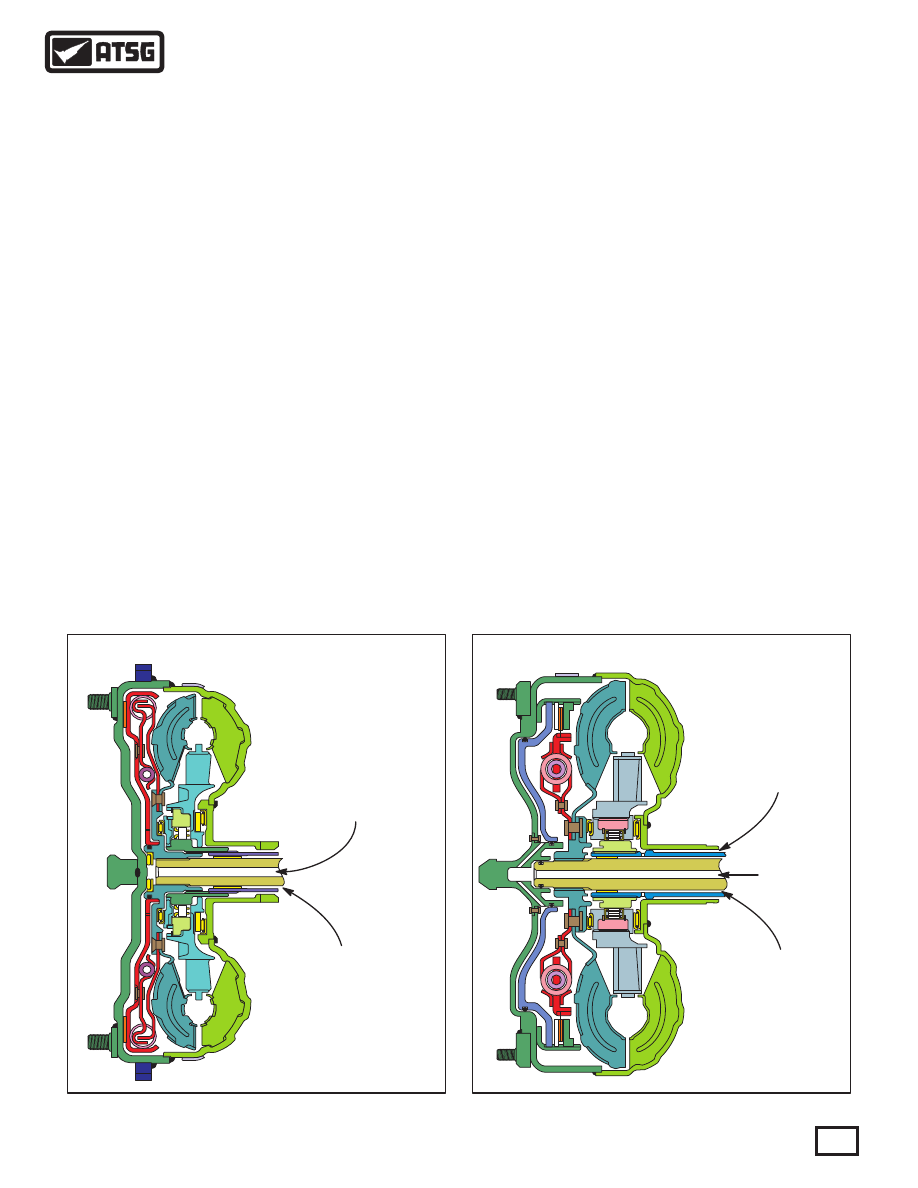
The "2 Port" Torque Converter functions like the
traditional lock-up converter and has a single floating
clutch plate.
Figure 143 below illustrates how the clutch and
damper are riveted to the converter turbine. Converter
fill fluid is fed into the release circuit from the TCC
valve in the valve body through the center of the turbine
shaft where it is routed between the converter cover and
pressure plate. This fluid pressure keeps the converter
clutch released and fills the converter. When the clutch
is commanded on, fill fluid (release oil) is exhausted at
the TCC apply valve and converter pressure applies the
clutch against the converter cover.
Converter Clutch
Apply Pressure
enters through
the center of the
Turbine Shaft
Converter “Out” fluid
returns to the TCC
control valve in the VB
between the Turbine
Shaft and Stator Shaft
Converter “Out” fluid
returns to the TCC
control valve in the VB
between the Turbine
Shaft and Stator Shaft
Converter “In” fluid
enters the converter
between the Stator Shaft
and Converter Hub
Converter “In” fluid
enters the converter
through the center of
the Turbine Shaft
The "3 Port" Torque Converter is uniquely constructed
in that the converter clutch apply circuit is independent
to the converter in and out fluid. The converter may
also contain either 1 or 2 friction plates depending on
engine size.
Figure 144 below, illustrates how the converter clutch
apply piston contours to the flywheel side of the torque
converter cover. The friction plates lug to a hub splined
to the turbine shaft while the steel plates lug to the
converter cover. When the clutch is commanded on,
apply fluid is fed through the center of the turbine shaft
and fills the area between the converter cover and
piston. The piston applies the friction plates to the steel
plates locking the turbine shaft to the cover.
Converter fill is fed into the converter between the
converter hub that drives the pump gears and the stator
shaft. The fluid’s return path is between the stator shaft
and turbine shaft.
TCC "3 PORT" HYDRAULIC OPERATION
TORQUE CONVERTER DIFFERENCES
"3 PORT" DESIGN
"2 PORT" DESIGN
Note: The Oil Pump, Turbine Shaft and Spacer
Plate are unique to the 2 Port Converter. Refer to
Figure 145 & 146 for dimensional differences.
Refer to Page 124 for spacer plate differences and
identification.
Note: The Oil Pump, Turbine Shaft and Spacer
Plate are unique to the 3 Port Converter. Refer to
Figure 145 & 146 for dimensional differences.
Refer to Page 124 for spacer plate differences and
identification.
Figure 143
Figure 144
79
Technical Service Information
There are two different types of torque converters used
in the "09D" transmission that changes some of the
internal parts. One is a "2 Port" design and the other is a
"3 Port" design, and refers to the number of fluid
passages needed to function properly.