Volkswagen 01M Transmission. Manual - part 58
 

  Index      Volkswagen     Volkswagen 01M Transmission - service manual 2001 year


Search              


Content   ..  56  57  58  59   ..


Volkswagen 01M Transmission. Manual - part 58


91

Technical Service Information

COMPONET REBUILD (CONT'D)

VALVE BODY ASSEMBLY

A-3

AISIN

AISIN

AISIN

AISIN

8 8

6 0

8 8

6 0

8 8

6 0

8 8

6 0

1

1

1

1

9AN

3K

017

55

9A

N3

K01

762

8BA

3K0

16

31

9AN

3K

01748

9AN3K

01742

4AM3K03O1

8

2

2

2

2

AISIN

AISIN

AISIN

AISIN

8 8

6 0

8 8

6 0

8 8

6 0

8 8

6 0

1

1

1

1

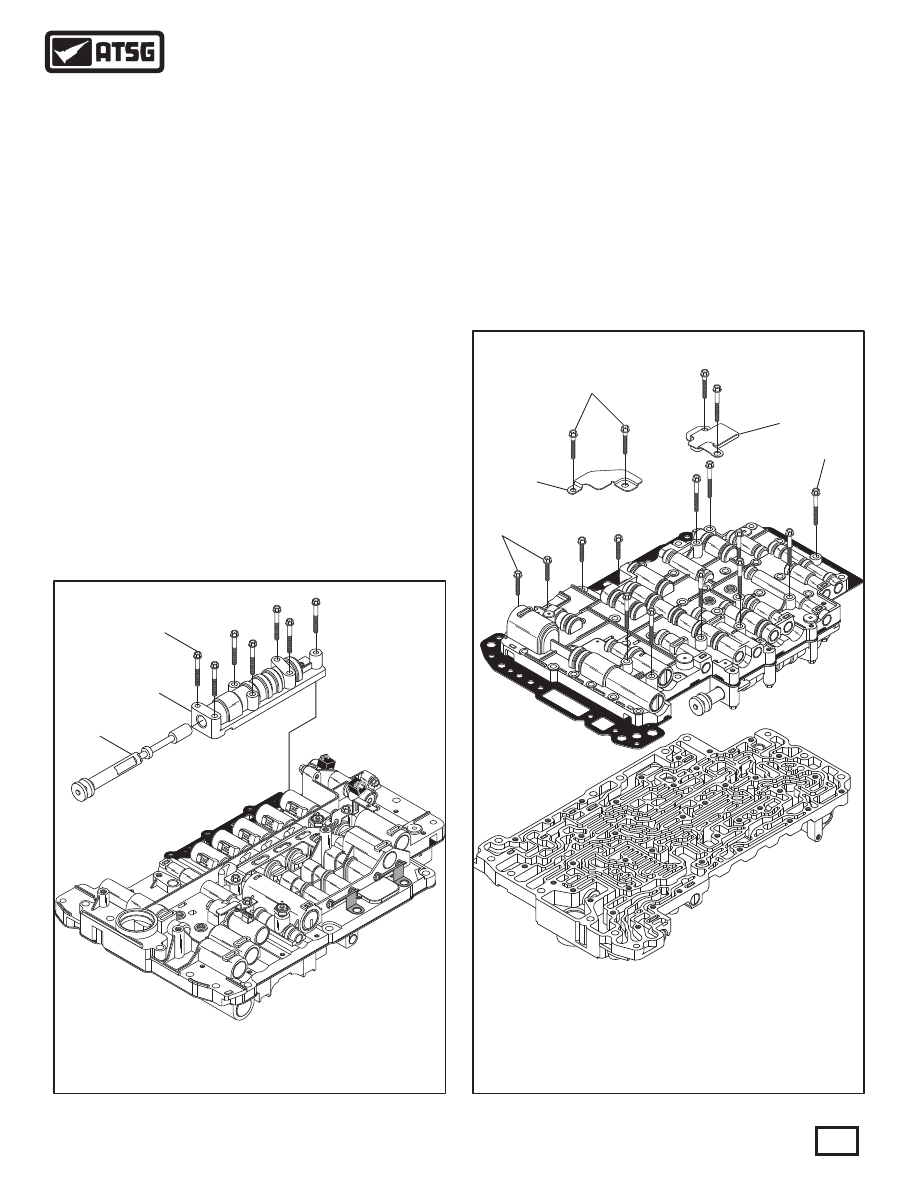
     1. Lay the valve body assembly on a flat work
       surface, as shown in Figure 167.
     2. Remove the seven bolts retaining the manual
             valve body, as shown in Figure 167.
     3. Remove the manual valve body and manual
       valve, as shown in Figure 167.
     4. Turn the valve body assembly over, as shown
       in Figure 168.
     5. Remove the 39 upper to lower valve body 
       bolts, as shown in Figure 168.
       Note: There are three different lengths of
       these bolts  See Legend in Figure 168.
     6. Remove the two oil baffles, as shown in
       Figure 168.
     7. Seperate the upper valve body, spacer plate 
       and lower valve body.

Figure 168

Figure 167

 770  MANUAL VALVE.
 771  MANUAL VALVE BODY CASTING.
 772  MANUAL VALVE BODY RETAINING BOLT, 38 MM (1.496") (7 REQ).

 668  UPPER VB TO LOWER VB BOLT, 22 MM (.866") (4 REQUIRED).
 669  UPPER VB TO LOWER VB BOLT, 28 MM (1.102") (25 REQUIRED).
 670  UPPER VB TO LOWER VB BOLT, 40 MM (1.574") (10 REQUIRED).
 671  OIL BAFFLE NUMBER 2.
 672  OIL BAFFLE NUMBER 1.

770

668

669

670

671

672

771

772

Continued on Page 92

Special Note: This valve body has proven to have 
very high bore wear and Sonnax® has available 
several line-ups that may save you from having to 
purchase a new valve body.

AISIN

AISIN

AISIN

AISIN

8 8

6 0

8 8

6 0

8 8

6 0

8 8

6 0

1

1

1

1

4AM

3K0

3O18

9A

N3

K0176

2

9AN3

K0

1755

8B

A3K0

1631

9AN3K

01748

9A

N3K

01742

"09D" LOWER VALVE BODY, EXPLODED VIEW

600

601

602

603

604

605

606

607

608

609

610

611

612

613

614

616

617

618

619

620

621

622

625

624

625

625

625

625

625

626

627

628A

629

630

631

632

633

634

635

636

637

638

639

640

641

642

643

644

645

646

647

648

649

650

651

652

653

654

655

656

657

658

628B

615

VALVE BODY ASSEMBLY (CONT'D)

     8. Disassemble lower valve body and place valves,
             springs, bore plugs and retainers on appropriate
       trays exactly as they are removed, as shown in
             Figure 169. Small parts are shown in Figure 172.
       Note: Tag the "Linear" solenoid locations on
       removal, as they are position sensitive.
     9. Clean all lower valve body parts thoroughly and
       dry with compressed air.
       Note: Do not submerge solenoids in solvent.

Continued on Page 93

Figure 169

92

Technical Service Information

See Legend Figure 170

See Legend Figure 170

ADJUSTABLE

PLUG

ADJUSTABLE

PLUG

9
AN3

K0

17

6
2

Note: Measure

Plug depth before

plug is removed

Caution: 
   There are 4 adjustable plugs screwed into the valve 
body casting at the end of the clutch regulating bores, 
as shown in Figure 169, along with two clips that are 
not necessary to remove.   If removal does become 
necessary, measure plug depth before plug is removed 
as it is a critical adjustment. 

 600  LOWER VALVE BODY CASTING.
 601  SECONDARY PRESSURE REGULATOR VALVE.
 602  SECONDARY PRESSURE REGULATOR VALVE SPRING (RED).
 603  SECONDARY PRESSURE REGULATOR VALVE ADJUSTMENT PLUG.
 604  SECONDARY PRESSURE REGULATOR VALVE ADJUSTMENT RETAINER.
 605  NUMBER 1 REL AY VALVE.
 606  NUMBER 1 REL AY VALVE SPRING (NONE).
 607  NUMBER 1 REL AY VALVE RETAINER.
 608  N93 P WM LINE PRESSURE CONTROL SOLENOID.
 609  N92 P WM K1 CLUTCH CONTROL SOLENOID.
 610  N90 P WM K3 CLUTCH CONTROL SOLENOID.
 611  N283 P WM B1 CLUTCH CONTROL SOLENOID.
 612  N282 P WM K2 CLUTCH CONTROL SOLENOID).
 613  P WM SOLENOID RETAINER PINS  (6 REQUIRED).
 614  K1 CLUTCH REGULATOR VALVE SPRING (RED).
 615  K1 CLUTCH REGULATOR VALVE.
 616  K3 CLUTCH REGULATOR VALVE SPRING (NONE).
 617  K3 CLUTCH REGULATOR VALVE.
 618  B1 CLUTCH REGULATOR VALVE SPRING (NONE).
 619  B1 CLUTCH REGULATOR VALVE.
 620  K2 CLUTCH REGULATOR VALVE SPRING (NONE).
 621  K2 CLUTCH REGULATOR VALVE.
 622  N89 ON/OFF SOLENOID.
 624  N91 P WM TCC CONTROL SOLENOID PIN RETAINER.
 625  RETAINING BOLTS, 12 MM (0.472") LONG  (6 REQUIRED).
 626  TRANSMISSION TEMP SENSOR RETAINING BRACKET.
 627  N93, N90, N92, N283, N282 SOLENOID PIN RETAINER.
 628A  B2 PRESSURE SWITCH   (NOT USED IN ALL MODELS).
 628B  K1 PRESSURE SWITCH   (NOT USED IN ALL MODELS).
 629  N88 ON/OFF SOLENOID.
 630  K2 ACCUMULATOR PISTON.
 631  K2 ACCUMULATOR PISTON OUTER SPRING (NONE).
 632  K2 ACCUMULATOR PISTON INNER SPRING (GRAY).
 633  K2 ACCUMULATOR PISTON BORE PLUG.
 634  K2 ACCUMULATOR PISTON BORE PLUG RETAINER.
 635  B1 ACCUMULATOR PISTON.
 636  B1 ACCUMULATOR PISTON OUTER SPRING (NONE).
 637  B1 ACCUMULATOR PISTON INNER SPRING (GRAY).
 638  B1 ACCUMULATOR PISTON BORE PLUG.
 639  B1 ACCUMULATOR PISTON BORE PLUG RETAINER.
 640  FORWARD ENGAGEMENT ACCUMULATOR SPRING NONE).
 641  FORWARD ENGAGEMENT ACCUMULATOR PISTON.
 642  FORWARD ENGAGEMENT ACCUMULATOR BORE PLUG.
 643  FORWARD ENGAGEMENT ACCUMULATOR BORE PLUG RETAINER.
 644  K1 SWITCH VALVE SPRING (PINK).
 645  K1 SWITCH VALVE.
 646  K1 SWITCH VALVE BORE PLUG.
 647  K1 SWITCH VALVE BORE PLUG RETAINER.
 648  N91 P WM TCC CONTROL SOLENOID.
 649  N93/LINE PRESSURE SOLENOID ACCUMULATOR PISTON.
 650  N93 ACCUMULATOR PISTON OUTER SPRING (NONE).
 651  N93 ACCUMULATOR PISTON INNER SPRING (GRAY).
 652  N93 ACCUMULATOR PISTON BORE PLUG.
 653  N93 ACCUMULATOR PISTON BORE PLUG RETAINER.
 654  K3 ACCUMULATOR PISTON.
 655  K3 ACCUMULATOR PISTON OUTER SPRING (NONE).
 656  K3 ACCUMULATOR PISTON INNER SPRING (GRAY).
 657  K3 ACCUMULATOR PISTON BORE PLUG.
 658  K3 ACCUMULATOR PISTON BORE PLUG RETAINER.
 659  ROUND SCREENS   (OPEN SIDE FACES SPACER PLATE)  (2 REQ).
 660  VALVE BODY SPACER PLATE.
 661  OVAL SCREEN   (OPEN SIDE FACES SPACER PLATE).
 662  K3 EXHAUST CHECK VALVE, 9.96 MM (.392") DIAMETER. 
 663  K3 EXHAUST CHECK VALVE SPRING   (WHITE).
 664  REGUL ATED EXHAUST CHECK VALVE, 9.96 MM (.392") DIA. 
 665  REGUL ATED EXHAUST CHECK VALVE SPRING  (WHITE).
 666  B2 CLUTCH PLASTIC CHECK VALVE ASSEMBLY. 
 667  FORWARD/K2 PLASTIC CHECK VALVE ASSEMBLY. 

SPRING NUMBER 602
Free Length = 1.043"
Spring Diameter = .623"
Wire Diameter = .052"
Approx Coils = 6 (RED)

SPRING NUMBER 616
Free Length = .860"
Spring Diameter = .235"
Wire Diameter = .032"
Approx Coils = 13 (NONE)

SPRING NUMBER 618
Free Length = .860"
Spring Diameter = .235"
Wire Diameter = .032"
Approx Coils = 13 (NONE)

SPRING NUMBER 620
Free Length = .860"
Spring Diameter = .235"
Wire Diameter = .032"
Approx Coils = 13 (NONE)

SPRINGS 631, 636, 650, 655,
Free Length = 1.085"
Spring Diameter = .628"
Wire Diameter = .082"
Approx Coils = 6.5 (NONE)

SPRINGS 632, 637, 651, 656,
Free Length = 1.093"
Spring Diameter = .430"
Wire Diameter = .062"
Approx Coils = 8.5 (GRAY)

SPRING NUMBER 640
Free Length = 2.456"
Spring Diameter = .775"
Wire Diameter = .075"
Approx Coils = 10 (NONE)

SPRING NUMBER 644
Free Length = 1.090"
Spring Diameter = .280"
Wire Diameter = .025"
Approx Coils = 11 (PINK)

SPRING NUMBER 614
Free Length = 1.018"
Spring Diameter = .235"
Wire Diameter = .025"
Approx Coils = 14 (RED)

SPRING NUMBER 606
Free Length = 1.560"
Spring Diameter = .355"
Wire Diameter = .025"
Approx Coils = 13 (NONE)

LOWER VALVE BODY SPRING SPECIFICATIONS

SPRING NO. 665
Free Length = .600"
Spring Diameter = .248"
Wire Diameter = .023"
Approx Coils = 11 (WHITE)

SPRING NO. 663
Free Length = .600"
Spring Diameter = .248"
Wire Diameter = .023"
Approx Coils = 11 (WHITE)

LOWER VALVE BODY SPRING SPECIFICATIONS

SMALL PARTS, WORM TRACK SIDE

FIGURE 169 AND 172 LEGEND

93

Technical Service Information

Figure 170

Figure 171

SPECIAL NOTE: VALVE NAMES SHOWN WERE

ASSIGNED BY ATSG BASED ON THEIR FUNCTION.

 10. Inspect all lower valve body parts thoroughly for
       any wear and/or damage.
       Note: See observed spring specs in Figure 171.
 11. Assemble the lower valve body parts exactly as 
             shown in Figure 169, and lube with the proper
       ATF as they are installed.
 12. Torque the solenoid retaining bracket bolts to
       10 N·m (89 in.lb.).

VALVE BODY ASSEMBLY (CONT'D)

Continued on Page 94

ENLARGED VIEW

ENLARGED VIEW

"09D" LOWER VALVE BODY SMALL PARTS, EXPLODED VIEW

659

660

661

662

663

664

665

666

667

600

94

Technical Service Information

Figure 172

VALVE BODY ASSEMBLY (CONT'D)
 13. Assemble the worm track small parts into lower
       valve body exactly, as shown in Figure 172.
 14. Disassemble upper valve valve body and place
             valves, springs, bore plugs and retainers on
       appropriate trays exactly as they were removed,
             as shown in Figure 173. Small parts are shown
       in Figure 175.
 15. Inspect all upper valve body parts thoroughly for
       any wear and/or damage.
       Note: See spring specs in Figure 176.

         Caution: Solenoid modulator valves (725), (733) 
         have high failure rates. Check bores carefully.
         Available from Sonnax®, see Figure 173. 
 16. Assemble the upper valve body parts exactly as
             shown in Figure 173, and lube with the proper
       ATF as they are installed.
       Note: Retainer for bore plug 681 will require
             some Trans-Jel® as it is not spring loaded.
 17. Install the worm track small parts into the upper
       valve body exactly as shown in Figure 175.

Continued on Page 98

See Legend Figure 170

See Legend Figure 170

Refer to Page 102 For

Spacer Plate Differences

Between The "2-Port" And

"3-Port" Converters

"A" OR "B"

SPACER PLATE

"A" OR "B"

SPACER PLATE

SMALL MAGNETS

IN BOTTOM OF

ROUND SCREENS

SMALL MAGNETS

IN BOTTOM OF

ROUND SCREENS


Content   ..  56  57  58  59   ..