Volkswagen 01M Transmission. Manual - part 60

A-
3
2
2
2
2
99
Technical Service Information
A-3
2
2
2
2
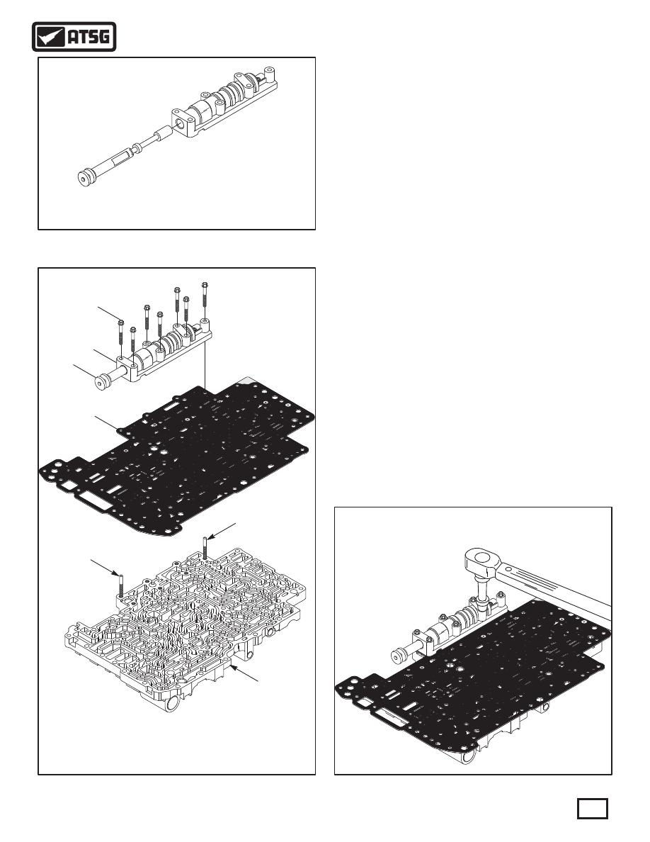
660 VALVE BODY SPACER PLATE WITH SCREENS.
770 MANUAL VALVE.
771 MANUAL VALVE BODY CASTING.
772 MANUAL VALVE BODY RETAINING BOLT, 38 MM (1.496") (7 REQ).
770 MANUAL VALVE.
771 MANUAL VALVE BODY CASTING.
2
2
2
2
770
660
ALIGNMENT
DOWEL
UPPER
VALVE BODY
ALIGNMENT
DOWEL
771
772
Figure 179
Figure 180
Figure 178
VALVE BODY ASSEMBLY (CONT'D)
COMPONENT REBUILD (CONT'D)
Continued on Page 100
20. Install the manual valve into the manual valve
body, as shown in Figure 178.
21. Lay the upper valve body on a flat work surface
with the worm track side facing up, as shown in
Figure 179.
22. Install two alignment dowels in the upper valve
body in the positions shown in Figure 179.
Note: Manufacture alignment dowels from
two extra manual valve body bolts.
23. With all small parts in their proper positions in
the upper valve body, install spacer plate over
alignment dowels and onto the upper valve body,
as shown in Figure 179.
Note: Refer to Page 102 for the spacer plate
differences between the "2-Port" and "3-Port"
torque converters.
24. While holding the spacer plate down against
spring pressure, install the manual valve body
and manual valve over alignment dowels, as
shown in Figure 179, and install four retaining
bolts in the center and "snug" them down.
25. Remove the alignment dowels, and install the
remaining three bolts. Tighten "snug".
26. Torque all seven manual valve body bolts to
10 N·m (89 in.lb.), as shown in Figure 180.
TORQUE MANUAL VALVE BODY BOLTS TO
10 N·M (89 IN.LB.)