Volkswagen 01M Transmission. Manual - part 66

3 U
123
Technical Service Information
TRANSMISSION ASSEMBLY (CONT'D)
Continued on Page 124
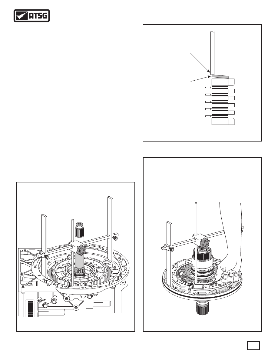
41. Install "H" gage on the transmission case pump
surface, as shown in Figure 220, and lower the
adjustment rod to the "high" point on the surface
of the cushion plate and tighten adjustment rod
locking knob.
Note: Tip of adjustment rod must be resting on
the "high" point of cushion plate, as shown in
Figure 221.
42. Now turn "H" gage over and set it on completed
oil pump assembly, as shown in Figure 223, with
adjustment rod over one leg of B1 clutch piston.
43. Measure with feeler gauge between adjustment
rod and B1 clutch piston to determine the B1
clutch clearance, as shown in Figure 223.
Note: There are no factory clutch clearance
specifications available, but the clearances
were the "traditional" .010" per friction plate
through-out this unit.
44. B1 clutch clearance should be approximately
.010" per friction plate installed, as shown in
Figure 223.
B1 CUSHION
PLATE
B1 CUSHION
PLATE
TIP OF ADJUSTMENT
ROD MUST BE RESTING
ON HIGH POINT OF
CUSHION PLATE
TIP OF ADJUSTMENT
ROD MUST BE RESTING
ON HIGH POINT OF
CUSHION PLATE
* 2
0
SGL
J0
0
0
3
7
Figure 220
Figure 222
Figure 221
B1 Clutch Clearance Should Be
Approximately .010" Per Friction
Plate Installed