Volkswagen 01M Transmission. Manual - part 65
 

  Index      Volkswagen     Volkswagen 01M Transmission - service manual 2001 year


Search              


Content   ..  63  64  65  66   ..


Volkswagen 01M Transmission. Manual - part 65


* 20SGL

 J00037

401

402

403

404

400

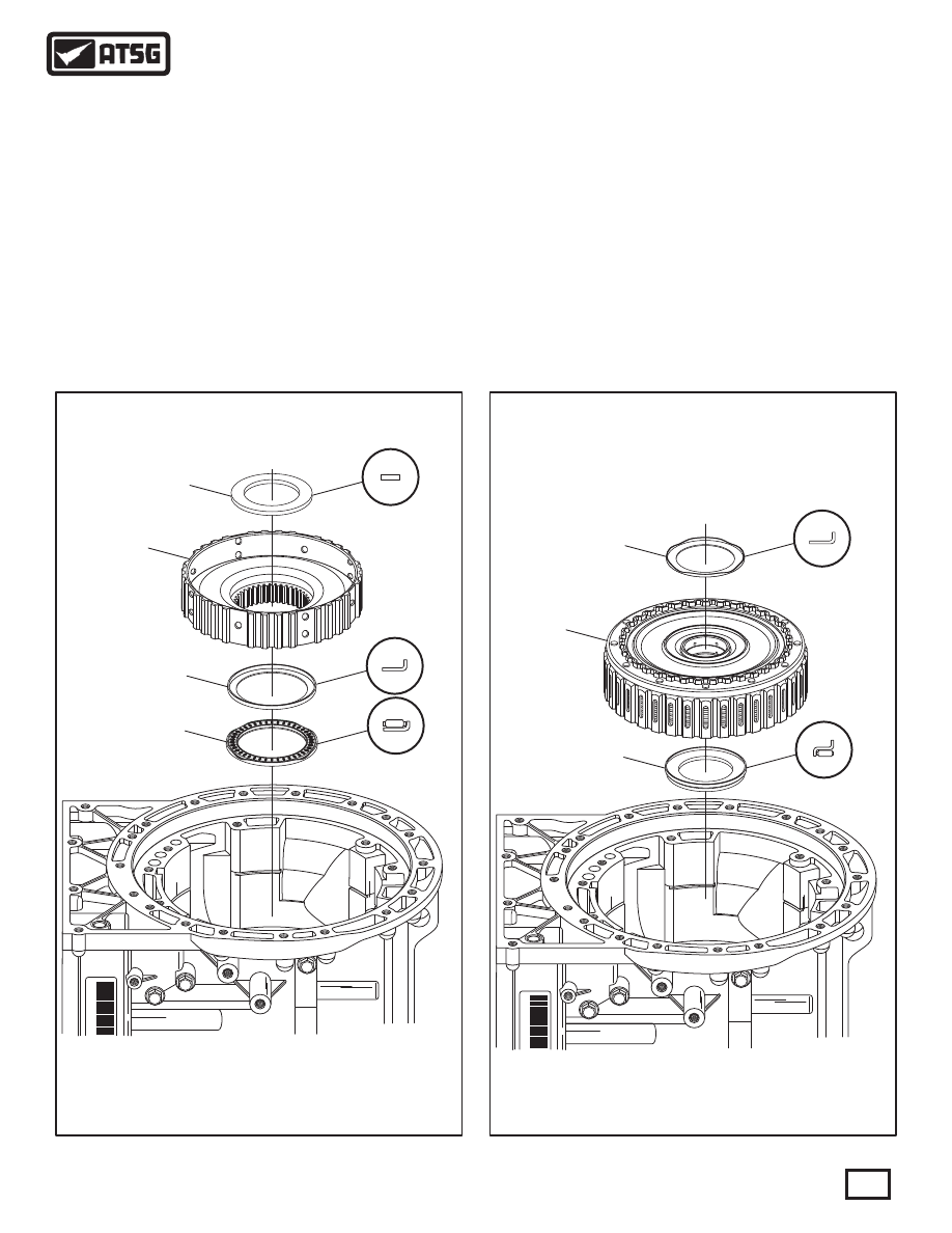
 401  NUMBER 7 THRUST BEARING RACE.
 402  K1 CLUTCH HUB.
 403  NUMBER 8 THRUST BEARING RACE.
 404  NUMBER 8 THRUST BEARING.

TRANSMISSION ASSEMBLY (CONT'D)

 25. Install the number 8 thrust bearing, as shown in
             Figure 212, on top of large sun gear and shell.
 26. Ensure the number 8 thrust bearing race is still
             stuck to the back of K1 clutch hub, as shown in
             Figure 212, and install K1 clutch hub assembly.
 27. Install number 7 thrust bearing race, as shown in
             Figure 212, in center of installed K1 clutch hub.
 28. Ensure the number 7 thrust bearing is still stuck
             to the back side of K1 clutch housing, as shown
       in Figure 213.

 29. Install completed K1 clutch housing, as shown 
             in Figure213, by rotating back and forth so the
       friction plates engage the clutch hub.
       Note: Ensure K1 clutch housing is fully seated.
 30. Install the number 6 thrust bearing race into the
             pocket on top of K1 clutch housing, as shown in
       Figure 213.

Continued on Page 120

Figure 212

Figure 213

* 20SGL

 J00037

229

 229  NUMBER 6 THRUST BEARING RACE.
 230  K1 CLUTCH HOUSING ASSEMBLY.
 400  NUMBER 7 THRUST BEARING.

230

119

Technical Service Information

228

THESE SPLINES

MUST BE ENGAGED

THESE SPLINES

MUST BE ENGAGED

* 20SGL

 J00037

Completed

Turbine Shaft And

Front Planet Assembly

* 20SGL

 J00037

72

200

    72  NUMBER 1 THRUST WASHER (PL ASTIC).
 200  K3 CLUTCH HOUSING ASSEMBLY.
 207  NUMBER 2 THRUST WASHER HARDENED RACE.

 228  NUMBER 6 THRUST BEARING.

207

Figure 215

Figure 214

TRANSMISSION ASSEMBLY (CONT'D)

 31. Ensure the number 6 thrust bearing is still stuck
             to back of the completed turbine shaft and front
             planetary assembly, as shown in Figure 214.
 32. Install the completed turbine shaft and front 
       planetary, as shown in Figure 214.
       Note: Splines of the front carrier must engage
             into K1 clutch housing (See Figure 214).
 33. Ensure number 2 thrust washer hardened race is
             still stuck to the K3 balance piston, as shown in
       Figure 215.
 34. Install completed K3 clutch housing, as shown 
             in Figure 215, by rotating back and forth until
       fully seated.

       Note: K3 frictions must engage on the front
             planetary carrier and internal splines of the K3
             clutch housing must engage external splines of
       sun gear shell.
 34. Install the number 1 thrust washer, as shown in
             Figure 215, engaging tabs into the slots of the
       K3 clutch housing.

Continued on Page 121

120

Technical Service Information

* 20SGL

 J00037

89

121

Technical Service Information

Figure 216

Figure 217

TRANSMISSION ASSEMBLY (CONT'D)

Continued on Page 122

 35. Now is the time to compare the measurement 
             you recorded during disassembly, as shown in
             Figure 216, to measurement that you now have.
       Note: These measurements should be the same.
             If not, there is a clutch, a bearing or bearing
       race not fully seated.
 36. Install the B1 clutch backing plate snap ring into
             the case, as shown in Figure 217, and ensure that
             it is fully seated in case groove.
 37. Install the B1 clutch backing plate, as shown in
             Figure 217, with the rounded edge facing up
       toward the friction plate.

20SGL

 J00037

3

4

5

1

2

MEASUREMENT TO

VERIFY RE-ASSEMBLY

MEASUREMENT TO

VERIFY RE-ASSEMBLY

88

 88  B1 CLUTCH BACKING PLATE, 4.6 MM (.181") THICK.
 89  B1 CLUTCH BACKING PLATE SNAP RING, 2.5 MM (.099").

ROUNDED EDGE

TOWARDS FRICTION

ROUNDED EDGE

TOWARDS FRICTION

BACKING

PLATE

APPLY

PLATE

B1 CLUTCH STACK-UP

S

t

t

t arre

9

8

0

* 20SGL

 J00037

B1 BACKING

PLATE

B1 BACKING

PLATE

84

85

86

87

 84  B1 CLUTCH "BELLVILLE" CUSHION PLATE.
 85  B1 CLUTCH APPLY PLATE, 4.0 MM (.158") THICK.
 86  B1 CLUTCH FRICTION PLATES (QTY VARIES).
 87  B1 CLUTCH STEEL PLATES, 2.0 MM (.079") THICK (QTY VARIES).

Figure 218

ROUNDED EDGE

TOWARDS FRICTION

ROUNDED EDGE

TOWARDS FRICTION

BACKING

PLATE

APPLY

PLATE

B1 CLUTCH STACK-UP

Figure 219

TRANSMISSION ASSEMBLY (CONT'D)

Continued on Page 123

 38. Install B1 clutch plates beginning with a friction
             plate and alternating with steel plates, as shown
             in Figure 219, until you have the proper amount
       installed as quantity may vary.
       Note: All friction plates should be soaked in
             proper fluid for 30 minutes before installing.
 39. Install B1 apply plate, as shown in Figure 219, 
             with the "rounded" edge facing down toward the
             last friction, as shown in Figure 218.
 40. Install the B1 "bellville" style cushion plate in 
       the direction shown in Figure 219.

122

Technical Service Information


Content   ..  63  64  65  66   ..