Volkswagen 01M Transmission. Manual - part 68
 

  Index      Volkswagen     Volkswagen 01M Transmission - service manual 2001 year


Search              


Content   ..  66  67  68  69   ..


Volkswagen 01M Transmission. Manual - part 68


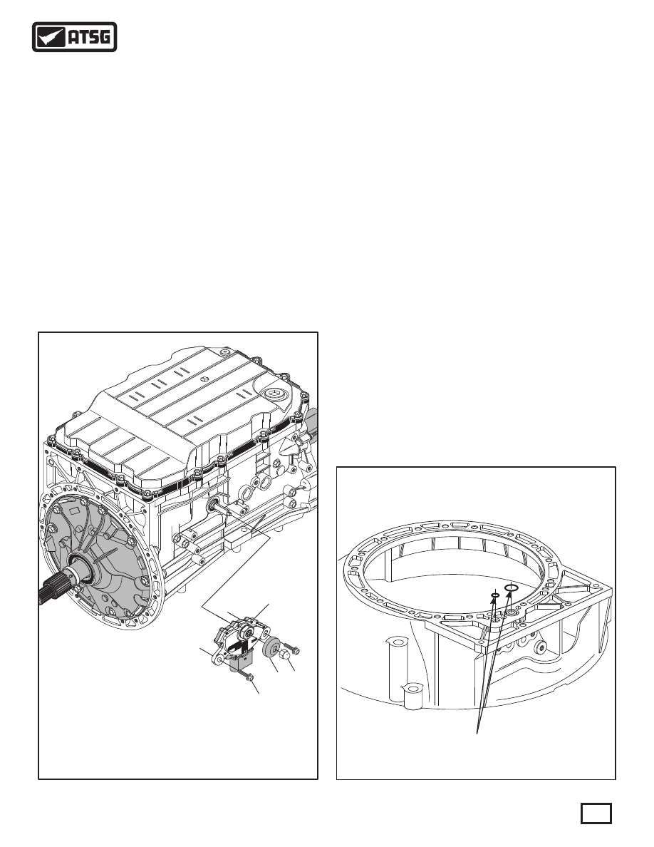
2 Different Size "O" Ring Seals

(Some Models Only)

A-3

2

2

2

2

AISIN

AISIN

AISIN

AISIN

8 8

6 0

8 8

6 0

8 8

6 0

8 8

6 0

1

1

1

1

9A

N3K

01755

9A

N3

K0

1762

8B

A3K

016

31

9A

N3K

01748

9A

N3K

017

42

4A

M

3K

03O

18

142

7

AT

JP

  57344

-01

09D 321 361

>Fe/Zn<

24

15

84

54

0

TR

A0

10

    5  TRANSMISSION MULTIFUNCTION (RANGE) SWITCH   (F125).
    6  SWITCH RETAINING BOLTS, 16.9 MM (0.665"), 2 REQUIRED.
   7  MOISTURE/DEBRIS SHIELD.
    8  MOISTURE/DEBRIS SHIELD ACORN RETAINING NUT.

5

6

7

8

Figure 241

Figure 242

 81. Some models of the "09D" family route line 
             pressure through the converter housing and will
             require two "O" ring seals on the back side of 
             converter housing, as shown in Figure 242.
 82. Retain the "O" ring seals with a small amount of
       Trans-Jel®.

TRANSMISSION ASSEMBLY (CONT'D)

Continued on Page 132

 78. Install the transmission range (multifunction) 
       switch, as shown in Figure 241.
       Note: If the range (multifunction) switch is
             removed or replaced, a position to the manual
             selector shaft must be set using a special tool
       available from Volkswagen.
 79. Set the position to the manual shaft and torque
             the 2 bolts to 10 N·m (89 in.lb.).
 80. Install the debris shield and acorn nut, as shown
       in Figure 241.

131

Technical Service Information

{

4 Behind Face Of Bell Housing Here

22 Total

* 20SGL

 J00037

142

7

AT

     2  CONVERTER HOUSING.
       3  CONVERTER HOUSING BO LTS, 30 MM (1.181")  (22 REQ).
 225  TURBINE SHAFT "O" RING   (3 PORT MODELS ONLY).

2

3

225

CONVERTER HOUSING BOLT LOCATIONS

 83. Install turbine shaft "O" ring seal into groove in
             turbine shaft, as shown in Figure 244.
       Note: Turbine shaft "O" ring is used on the 
       3 port converter models only.
 84. Install the torque converter housing, as shown in
       Figure 244.
 85. Install the 22 converter housing retaining bolts,
       as shown in Figure 244.
       Note: See Figure 243 for locations.
 86. Torque all 22 converter housing retaining bolts 
             to 27 N·m (20 ft.lb.), using a 12 MM socket.
       Note: Four of the converter housing bolts are
             behind the face of housing, as shown in
       Figure 243.
 87. Install the proper torque converter, as shown in
       Figure 245.

TRANSMISSION ASSEMBLY (CONT'D)

Figure 244

Figure 243

132

Technical Service Information

CONGRATULATIONS

YOU ARE FINISHED!

* 20SGL J00037

142

7

AT

1

    1  TORQUE CONVERTER ASSEMBLY.

Figure 245

133

Technical Service Information

Figure 246

TORQUE SPECIFICATIONS

Component

Oil Pump to Case

Oil Pump Cover to Pump Body

Converter Housing to Case

Manual Valve Body

Upper VB to Lower VB and Linear Solenoid Brackets

Park Rod Guide to Case

Inside Detent Spring to Case

Temp Sensor to Valve Body

Oil Pan Drain Plug

Valve Body to Case Bolts

8-Way and 14-Way Case Connectors to Case

Oil Pan to Case

Oil Screen to Valve Body

Oil "Check" Plug

2WD Mounting Plate

2WD Driveshaft Yoke Nut

Output Speed Sensor to Case and OSS Harness Bracket

Input Speed Sensor to Pump Cover and ISS Connector to Pump Body

Transmission Range (Multifunction) Switch to Case

N•m

28

20

18

13

28

10

10

28

97

20

11

97

11

97

28

11

11

11

11

28

55

82

11

6

10

Ft.Lb.

97

97

97

97

20

40

60

97

53

89

In.Lb.

20

89

89

20

Note: Some torque specifications are based on the findings in a virgin unit that was torn down.  The manufacturer
          does not provide any factory torque specifications.

THRUST BEARING AND THRUST W

ASHER L

OCA

TIONS


 NO

. 1: 

 THRUST W

ASHER

, OIL PUMP TO K3 CL

UT

CH HOUSING, WHITE PL

ASTIC, 4.78 MM (.188") THICK AND PROBABL

Y SELECTIVE.


 NO

. 2: 

 THRUST W

ASHER

, K3 CL

UT

CH HOUSING TO NUMBER 3 THRUST W

ASHER

, HARDENED RA

CE FOR NO

.3 THRUST W

ASHER

.


 NO

. 3: 

 THRUST W

ASHER

, FRONT SIDE OF FRONT CARRIER TO NO

. 2 HARDENED RA

CE IN K3 CL

UT

CH HOUSING, WHITE PL

ASTIC.


 NO

. 4: 

 THRUST W

ASHER

, REAR SIDE OF FRONT CARRIER TO FRONT RING GEAR THRUST W

ASHER

, WHITE PL

ASTIC.


 NO

. 5: 

 THRUST BEARING, FRONT SUN GEAR TO FRONT RING GEAR

.


 NO

. 6: 

 THRUST BEARING, FRONT RING GEAR TO K1 CL

UT

CH HOUSING.


 NO

. 7: 

 THRUST BEARING, K1 CL

UT

CH HOUSING TO K1 CL

UT

CH HUB.


 NO

. 8: 

 THRUST BEARING, K1 CL

UT

CH HUB TO L

ARGE REAR SUN GEAR AND DRIVE SHELL.


 NO

. 9: 

 THRUST BEARING, L

ARGE SUN GEAR AND DRIVE SHELL TO REAR PL

ANET

AR

Y CARRIER

.

 NO

. 10: 

 THRUST BEARING, SMALL SUN GEAR TO REAR PL

ANET

AR

Y CARRIER

.

 NO

. 11: 

 THRUST BEARING, REAR PL

ANET

AR

Y CARRIER TO K2 CL

UT

CH HOUSING.

 NO

. 12: 

 THRUST BEARING, K2 CL

UT

CH HOUSING TO OUTPUT SHAFT

.

 NO

. 13: 

 THRUST BEARING, OUTPUT SHAFT TO TRANSMISSION CASE.

No. 1

No. 3

No. 2

No. 5

No. 7

No. 8

No. 10

No. 1

1

No. 4

No. 6

No. 9

No. 12

No. 13

134

Technical Service Information

Figure 247


Content   ..  66  67  68  69   ..