Volkswagen 01M Transmission. Manual - part 116

9170
1
9
70
Appropriate
Size Block
VALVE BODY ASSEMBLY (CONT'D)
Continued on Page 95
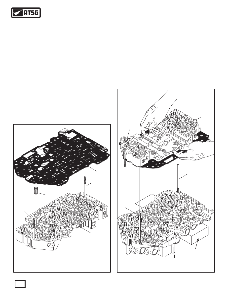
14. Install the plastic filter into the valve body spacer
plate, as shown in Figure 154, with the open end
towards spacer plate.
Note: Gaskets are moulded to all spacer plates.
15. Temporarily install two of the long accumulator
housing bolts through bottom of upper valve
body, as shown in Figure 154, for alignment of
the spacer plate.
16. With all small parts in place, carefully install the
spacer plate and filter assembly over alignment
bolts, as shown in Figure 154.
17. Place the completed lower valve body on a flat
work surface with an appropriate size block to
hold the lower valve body level, as shown in
Figure 155.
18. Install two "manufactured" (4T60-E pump bolt)
alignment dowels in the positions shown in
Figure 155.
319
252
(MAIN SPACER SIDE)
300
243
850
850
243
243
243
Figure 154
Figure 155
243 ACCUMULATOR 2 HOUSING TO UPPER V.B. (64 MM LENGTH)
252 UPPER VALVE BODY ASSEMBLY.
300 MAIN VALVE BODY SPACER PLATE.
319 PLASTIC FILTER FOR SOLENOID REGULATOR VALVES.
243 ACCUMULATOR 2 HOUSING TO UPPER V.B. (64 MM LENGTH)
850 'MANUFACTURED" (4T60-E PUMP BOLTS) ALIGNMENT DOWELS.
19. Clamp the spacer plate to upper valve body with
your hands and very carefully turn the assembly
over, as shown in Figure 155.
20. With the small parts installed in the lower valve
body, hands clamping small parts in place in the
upper valve body, very carefully install the upper
valve body and spacer plate over the alignment
dowels and onto the lower valve body, as shown
in Figure 155.
94
Technical Service Information