Volkswagen 01M Transmission. Manual - part 114
 

  Index      Volkswagen     Volkswagen 01M Transmission - service manual 2001 year


Search              


Content   ..  112  113  114  115   ..


Volkswagen 01M Transmission. Manual - part 114


115

118

118

113

116

REAR VIEW

112

111

117

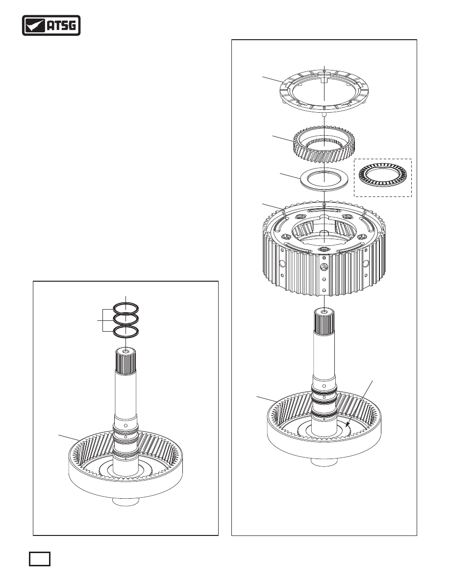
 115  INPUT SHAFT SEALING RINGS  (3 REQUIRED).
 118  FRONT PLANETARY RING GEAR AND INPUT SHAFT ASSEMBLY.

Figure 142

Figure 143

86

Technical Service Information

FRONT PLANETARY ASSEMBLY (CONT'D)

COMPONENT REBUILD (CONT'D)

   8. Install three new sealing rings in the grooves
       of input shaft, as shown in Figure 142.
   9. Install the front planetary carrier assembly into
       planetary ring gear, as shown in Figure 143, by
       rotating into position.
       Note: Ensure number 4 thrust washer and
       number 3 thrust bearing race are in place.
 10. Install the number 3 thrust bearing, as shown
       in Figure 143, with needles facing down.
 11. Install the front planetary sun gear, as shown
       in Figure 143, by rotating into position.
 12. Install the number 2 thrust washer, as shown
       in Figure 143, and retain with Trans-Jel®.
 13. Set the completed front planetary assembly
       aside for the final assembly process, as shown
       in Figure 144.

 111  NUMBER 2 THRUST WASHER.
 112  FRONT PLANETARY SUN GEAR.
 113  FRONT PLANETARY CARRIER ASSEMBLY.
 116  NUMBER 3 THRUST BEARING.
 117  NUMBER 3 THRUST BEARING RACE.
 118  FRONT PLANETARY RING GEAR AND INPUT SHAFT ASSEMBLY.

Componet Rebuild

Continued on Page 87

453

455

456

457

459

460

461

458

454

 453  CENTER SUPPORT CASTING.
 454  CENTER SUPPORT BALL BEARINGS  (2 REQUIRED).
 455  TRANSFER DRIVE GEAR.
 456  REAR PLANETARY RING GEAR INTERNAL SNAP RING.
 457  CENTER SUPPORT NUT LOCKING TAB.

 458  CENTER SUPPORT DRIVE GEAR RETAINING NUT.
 459  REAR PLANETARY RING GEAR HUB RETAINING SNAP RING.
 460  REAR PLANETARY RING GEAR HUB.
 461  REAR PLANETARY INTERNAL RING GEAR.

CENTER SUPPORT AND ASSOCIATED PARTS, EXPLODED VIEW

87

Technical Service Information

COMPLETED FRONT PLANETARY ASSEMBLY

Figure 144

Figure 145

CENTER SUPPORT ASSEMBLY

COMPONENT REBUILD (CONT'D)

   1. You can disassemble center support assembly
       using Figure 145 as a guide.
       Note: It is not necessary nor recommended to
       disassemble center support, as visual damage
       would require complete replacement anyway.
       If replacement is necessary, ensure that you
       recieve the proper tooth count for transfer
       drive gear.
   3. Clean all center support parts thoroughly and
       dry with compressed air.
   3. Inspect all center support parts thoroughly for
       any wear and/or damage, replace as necessary.

WARNING: At time of this printing, there are not 
any  new  "hard  parts"  available  from  the 
manufacturer for this unit. The only source will be 
used aftermarket suppliers.

   4. The torque specification on the retaining nut is
       approximately 34 N·m (25 ft.lb.).
   5. Set completed center support assembly aside
       for the final assembly process.

Component Rebuild

Continued on Page 88

900

960

961

962

Figure 146

Figure 147

FINAL DRIVE ASSEMBLY

TRANSFER/PINION GEAR ASSEMBLY

COMPONENT REBUILD (CONT'D)

COMPONENT REBUILD (CONT'D)

   1. Disassemble transfer driven gear/pinion gear
       assembly, using Figure 146 as a guide.
       Note: Press is required to remove the tapered
       roller bearings.
   3. Clean all transfer driven gear/pinion gear parts
       thoroughly and dry with compressed air.
   3. Inspect all transfer driven gear/pinion gear
       parts thoroughly for any wear and/or damage,
       replace as necessary.
       Note: If replacement is necessary, verify the
       tooth count on transfer gear and pinion gear.

   1. The final drive assembly is illustrated for you
       in Figure 147.
       Note: It is not necessary nor recommended to
       disassemble final drive, as visual damage
       would require complete replacement anyway.
       If replacement is necessary, ensure that you
       recieve the proper tooth count for ring gear.
   3. Clean all final drive parts thoroughly and dry
       with compressed air.
   3. Inspect all final drive parts thoroughly for any
       wear and/or damage, replace as necessary.

WARNING: At time of this printing, there are not 
any  new  "hard  parts"  available  from  the 
manufacturer for this unit. The only source will be 
used aftermarket suppliers.

WARNING: At time of this printing, there are not 
any  new  "hard  parts"  available  from  the 
manufacturer for this unit. The only source will be 
used aftermarket suppliers.

   4. Set the completed final drive assembly aside
       for the final assembly process.

   4. Install new tapered roller bearings as necessary
       as shown in Figure 146.
   5. Set transfer driven gear/pinion gear assembly
       aside for the final assembly process.

Component Rebuild

Continued on Page 89

TRANSFER/PINION GEAR EXPLODED VIEW

COMPLETED FINAL DRIVE ASSEMBLY

 960  TRANSFER DRIVEN GEAR/PINION GEAR SHAFT.
 961  TAPERED ROLLER BEARING  (CONVERTER COVER SIDE).
 962  TAPERED ROLLER BEARING  (CASE SIDE).

 900  FINAL DRIVE ASSEMBLY.

88

Technical Service Information

 240  LOWER V.B. TO ACCUMULATOR HOUSING 2 BOLT  (70 MM LENGTH).
 241  LOWER V.B. TO UPPER V.B. BOLT  (39.5 MM LENGTH).
 242  LOWER V.B. TO UPPER V.B. BOLT  (28 MM LENGTH).
 243  ACCUMULATOR 2 HOUSING TO UPPER V.B. (64 MM LENGTH)(3 REQ).
 244  ACCUMULATOR-2 HOUSING TO UPPER V.B. (52 MM LENGTH)(4 REQ).
 245  ACCUMULATOR-1 HOUSING TO UPPER V.B. (52 MM LENGTH)(4 REQ).
 246  ACCUMULATOR-1 HOUSING TO UPPER V.B. (64 MM LENGTH)(2 REQ).
 247  ACCUMULATOR-2 HOUSING ASSEMBLY.
 248  ACCUMULATOR-2 ASSEMBLY SPACER PLATE.
 249  ACCUMULATOR-1 HOUSING ASSEMBLY.
 250  ACCUMULATOR-1 ASSEMBLY SPACER PLATE.
 251  UPPER V.B. TO LOWER V.B. BOLTS  (21 MM LENGTH)(10 REQUIRED).
 252  UPPER VALVE BODY ASSEMBLY.
 254  LOWER VALVE BODY ASSEMBLY.
 300  MAIN VALVE BODY SPACER PLATE.

89

Technical Service Information

1

9

70

1

9

70

1

T

T1

917

0

T1

C

7CA

3

0070

8

7C

A3C

007

40

5BY

A013

7

3

1

5B

X3A0

170

6

5C

B3B

00400

C0

4A

U3

0100

"09G" VALVE BODY EXPLODED VIEW

240

241

242

243

243

247

248

252

300

254

243

244

246

249

250

251

245

Figure 148

Figure 149

VALVE BODY ASSEMBLY

COMPONENT REBUILD (CONT'D)

   1. Disassemble the main valve body components
       using Figure 148 and 149 as a guide.
       Note: All valve body bolt lengths are found in
       the legend and must be positioned properly.
   2. Clean all valve body components thoroughly and
       dry with compressed air.
       Note: Do not submerge solenoids in solvent.
   3. Inspect all valve body components thoroughly
       for any damage.

See Legnd in Figure 148

Continued on Page 91


Content   ..  112  113  114  115   ..