Volkswagen 01M Transmission. Manual - part 100
 

  Index      Volkswagen     Volkswagen 01M Transmission - service manual 2001 year


Search              


Content   ..  98  99  100  101   ..


Volkswagen 01M Transmission. Manual - part 100


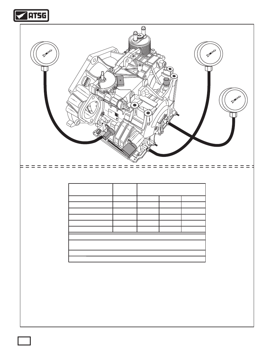
"Observed" K1 and K2 Pressures, at operating temperature with a new valve body installed.
  Initial engagement N to D;  K1 pressure at idle is 56-60 psi.
  Under acceleration in D;    K1 pressure is 75-80 psi.
  Before the 1-2 shift in D;   K1 pressure raises to 140-150 psi.
  When shift is completed;   K1 pressure settles at 80-90 psi in 2nd gear.
  Before the 2-3 shift in D;  K1 pressure raises to 95-100 during 2-3 shift and settles at 70 psi in 3rd.
  Before the 3-4 shift in D;  K1 pressure raises to 140 psi,  K2 pressure still under 4 psi.  Then K1 pressure begins to drop
                                             and K2 pressure begins to rise with both settling at 85-90 psi in 4th gear.
  During  4-5 shift in D;     K2 pressure raises to 190-200 psi, K1 pressure raises to 155-160 psi, then K1 drops to 40 psi,
                                            (While K2 is 170), then drops gradually to less than 2 psi, and K2 settles at 140 psi in 5th gear.
  During  5-6 shift in D;    K2 pressure drops to 110-120 in 6th gear.

30

Technical Service Information

"Observed" Pressure Specifications

Selector

Lever

"D" Idle

"D" Idle (Tiptronic)

"D" Stall*

"D" Stall (Tiptronic)*

"R" Idle

"R" Stall*

* "D" & "R" Stall, at approx 2300 rpm, the PCM cuts fuel to engine.

K1 & B2

K1

K3

B2

K1 & B2

K1 & B2

K1 & B2

K3 & B2

K3 & B2

54-60

0.9

104-106

23-28

146-160

187-190

0.9

53-55

80-85

80-85

270-275

270-275

Other "Observed" Pressures

Lube Pressure 4-8 psi,  8-10 psi in 6th gear

TCC Release 80-90 psi in Reverse

Taps

Required

Specifications in psi

LINE PRESSURE SPECIFICATIONS

Figure 34

G

S

F

AU

FA

AU

FA

V

  A

W

G

V

  A

W

G

GZ


G

  2

30


80

3

03

C

T

16

2

02

8

9


G

30

0

5

0

0

3

H


5

44

2

73


0

1

- 1

4

5


0

1

-

T

68

0

C

02

3

1

2

O

Z

0

0

H

3


5

0

 3

9

0

G

1

0

0

4

l

ll

l

l

l

l

l

l

l

l

l

l

l

l

l

l

l

l

l

l

l

l

l

l

l

l

l

l

l

l

l

l

l

l

l

l

l

l

ll

l l

ll

l l

l

l

l

ll

l

l

l

l

l

l

l

l

l

l

l

l

l

l

l

l

l

l

l

l

l

l

l

l

l

l

l

l

l

l

l

l

l

l

l

l

ll

l l

ll

l l

l

l

l

ll

l

l

l

l

l

l

l

l

l

l

l

l

l

l

l

l

l

l

l

l

l

l

l

l

l

l

l

l

l

l

l

l

l

l

l

l

ll

l l

ll

l l

l

l

Forward

(300 lb Gauge)

Forward Tiptronic

& Reverse

(300 lb Gauge)

Reverse

(300 lb Gauge)

Many Thanks To;

Jesse Zacharias

For Providing Us
With These Specs

To Share

Many Thanks To;

Jesse Zacharias

For Providing Us
With These Specs

To Share

31

Technical Service Information

   There are two distinctly different style lubrication 
systems used in TF-60SN (09G/09M) transaxles.  As 
a  result,  there  are  2  different  transaxle  cases,  2 
different  converter  housings  and  2  different  valve 
body to case spacer plates.

  Some models use an ATF cooler that is mounted  on 
the converter housing and integrated into the engine 
cooling  circuit,  as  shown  in  Figure  35.    With  this 
arrangement,  cooler  fluid  is  sent  directly  into  the 
cooler and returned to the lube circuit.
   Engine coolant is piped to the integral cooler and 
returned  to  the  cooling  system  with  a  constant 
circulation.

  Some models use an ATF cooler that is mounted in a 
remote location, also shown in Figure 35, and cooler 
fluid must be sent via traditional cooler lines to the 
cooler.  This requires entry and exit points  located in 
the transaxle case, and their locations are shown in 
Figure 35.

G

S

F

AU

FA

U

A

FA

A

VW


G

 A

VW


G


   28

0

G

Z

03

G


3

3

2

2

0

68

0

T

1

C

9

0

0

H

3

  35

G

0

5

4

3-

0

7

4


2

0

-

-

4


5


1

3

1

0

T

2

8

C2

0

6

O

Z


H

30

03

0

5

0

G

9

0

1

4

0

G

S

F

AU

FA

U

A

FA

A

G

V

 A

VW


G


  2

0

G


80

3

GZ


3

3

2

2

0

0

68

C

T

1

9

0

0

3

 0

H

0

35

5

4 -

34

  02

7


0

-

-

4


5


1

1

3

T

2

8

0

2

0

6

C

O

Z


H

30


3

0

0

5

0

G

9

0

1

4

0

To Remote

Cooler

From Remote

Cooler

Engine Coolant To

Integral Cooler

Engine Coolant From

Integral Cooler

Integral Cooler

Remote Cooler

Example

COOLER INFORMATION

COOLER INFORMATION

Integral Cooler

Remote Mounted Cooler

    Caution:    If  a  mis-match  of  any  of  these  parts 
occur,  lubrication  fluid  is  lost  causing  immediate 
failure of the transaxle drive train.
   Pay very close attention to the passage ID section 
that  follows,  as  it  provides  a  way  to  identify  these 
parts, to avoid disaster.

Figure 35

Fluid Fill

Pipe

Note: All Transaxles

Are Not Equipped With

Fluid Fill Device

Figure 36

CASE PASSAGE IDENTIFICATION (VALVE BODY SIDE) WITH "INTEGRAL COOLER"

CASE PASSAGE IDENTIFICATION (VALVE BODY SIDE) WITH "REMOTE COOLER"

Pump Outlet

(Line)

Pump Outlet

(Line)

Front Planet

Lube (1)

Cooler Return

To VB (8)

Thru Pump

Case Identification

For Transaxle With

Cooler Attached To

Converter Cover, As

This Passage Is Not

In The Remote Cooler

Transaxle Case

Case Identification

For Transaxle With

Remote Cooler, As

This Passage Is Not

In the Integral Cooler

Transaxle Case

B1

B1

K1

K1

K3

K3

Front Planet

Lube (1)

Remote Cooler

Return To VB (2)

Cooler/Lube

Filter

K2

B2

To TCC Release

Pressure Tap

To K1 Pressure Tap

Lube

Pump Inlet

(Suction)

Pump Inlet

(Suction)

Blocked By Pump

Blocked By Pump

TCC Release

TCC Release

TCC Apply

TCC Apply

To Remote

Cooler From VB (1)

B2

K2

To K1 Pressure Tap

Lube

To Cooler

From VB (1)

Differential Lube

From VB (1)

Differential Lube

From VB (1)

To TCC Release

Pressure Tap

32

Technical Service Information

Figure 37

CONVERTER COVER PASSAGE IDENTIFICATION WITH "INTEGRAL COOLER"

CONVERTER COVER PASSAGE IDENTIFICATION WITH "REMOTE COOLER"

Converter Cover

(Case Side)

0  

240

40

5

. 7

2433 a

20

0

To Remote Cooler

From Pump (9)

From Remote Cooler

Return To VB (9)

Pipe To Remote Cooler

From VB (4)

To Remote Cooler

From VB (3)

Differential Lube

From VB (3)

To Remote

Cooler (5)

Remote Cooler

(Example)

Converter Cover

(Case Side)

Integral

Cooler

Cooler Return Pipe

To VB (2)

Thru Pump

Cooler Return

To VB (1)

Thru Pump

Cooler Return

To VB (3)

Thru Pump

Cooler In

From VB (5)

Pipe To Cooler

From VB (4)

To Cooler

From VB (3)

Differential Lube

From VB (3)

33

Technical Service Information


Content   ..  98  99  100  101   ..