Volkswagen 01M Transmission. Manual - part 103
 

  Index      Volkswagen     Volkswagen 01M Transmission - service manual 2001 year


Search              


Content   ..  101  102  103  104   ..


Volkswagen 01M Transmission. Manual - part 103


SAFETY PRECAUTIONS

TRANSAXLE DISASSEMBLY

    Service  information  provided  in  this  manual  by 
ATSG is intended for use by professional, qualified 
technicians.   Attempting repairs or service without 
the appropriate training, tools and equipment could 
cause injury to you or others.
    The  service  procedures  we  recommend  and 
describe  in  this  manual  are  effective  methods  of 
performing service and repair on this unit.  Some of 
the procedures require the use of special tools that 
are designed for specific purposes.
   This manual contains CAUTIONS that you must 
observe carefully in order to reduce the risk of injury 
to  yourself  or  others.    This  manual  also  contains 
NOTES that must be carefully followed in order to 
avoid improper service that may damage the vehicle, 
tools and/or equipment.

AU

A

F

AU

FA

W

V

  AG


VW

AG


  2

03

GG

803


3

02

0

C2

168

T

 0

0

5

09

G

3

 03

H

57

  2

34

40- 


405

 -

- 1

1

1

68

0

C2

T0

3

21

O

Z

0

5

3


3

0

0

H

9

0

G

100

4

Q

A

E

A

Torque

Converter

Code Letters

TORQUE CONVERTER

   1. The transaxle should be steam cleaned on the 
       outside, to remove any dirt and grease before
       disassembly begins.
   2. This transaxle can be disassembled very easily
       on a work bench without the benefit of holding
       fixture for rotation.
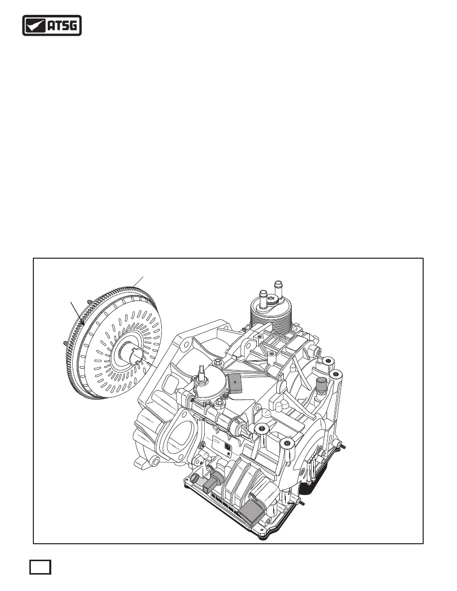
   3. Remove the torque converter from transaxle,
       as shown in Figure 50.
       Caution:  Use care when removing the torque
       converter, to avoid personal injury and/or
       damage to converter, as it is heavy.
   4. Record the torque converter code letters, as
       shown in Figure 50, for future reference.

Figure 50

Continued on Page 43

   Note: The illustrations provided in the Assembly
   and Disassembly section, are of a VW "09G" 
   model with the integral cooler, but procedures
   are the same on "09K" and "09M" models.

42

Technical Service Information

WARNING:  There  are  not  any  new  "hard  parts" 
available from the manufacturer for this unit. Only 
source will be used aftermarket suppliers.

TRANSAXLE DISASSEMBLY (CONT'D)

   5. Remove the 2 transaxle range switch retaining
       bolts and range switch, as shown in Figure 51.
       Note: The contact lever adjusting nut must
       not be loosened  (See Figure 51).
   6. Remove the integral cooler (if equipped) and 
       set aside for flushing.

   7. Remove and discard the 2 filter seals (4) & (6),
       as shown in Figure 51.
       Note: Notice that some models are equipped
       with a flow control distributor pipe in the
       supply side of cooler, as shown in Figure 51.

Continued on Page 44

AU

FA

AU

FA

V

  AG

W

VW

  AG

0

0

GG

Z   

28

3

3

0

2

3

T0

1

8

C

2

6

09

G

0

H

 3

0 3

5

0

5

3

  0

7

44  2

-

 1

 -

4

5

 -


0

1

1

6

03

2

8

C

T0

21

O

Z

  03

3


5H

00

09

G

1

0

0

4

    For  flow  control,  a  distributor  pipe  is 
installed  into  the  supply  side  of  the 
Integral Cooler on some models only.
NOTE:   Do not install distributor pipe in 
the return side of the Integral Cooler.

   2  TRANSAXLE RANGE SWITCH.
   3  TRANSAXLE RANGE SWITCH RETAINING BOLTS  (2 REQUIRED).
   4  INTEGRAL COOLER TO CASE SPECIAL "O" RING SEAL.
   5  INTEGRAL COOLER ASSEMBLY.
   6  "O" RING SEAL.
   7  FLAT WASHER.
   8  CONE SHAPED LOCKING WASHER.
   9  INTEGRAL COOLER RETAINING BOLT.
 10  INTEGRAL COOLER FLOW CONTROL PIPE  (SOME MODELS).

2

CONTACT LEVER

ADJUSTING NUT

3

4

5

6

7

8

9

10

Figure 51

43

Technical Service Information

0

917

1

T

7C

0

0

3C0

7

8

A

007

4

7CA

3C

0

0

5B

3A

1371

Y

6

5

X3

01

7

B

A

0

5C

B3

B0

0

04

0

4A

3

0010

0

U

C

0

917

T1

C

7

3C0

07

08

A

0

4

7CA

3C0

70

5B

3A01371

Y

5

X3

01

7

6

B

A

0

5C

B3

B0

0

04

0

4A

0

0

U3

C0

1

0

TRANSAXLE DISASSEMBLY (CONT'D)

   8. Remove the bottom oil pan bolts (8 on "09G")
       and remove the bottom oil pan, as shown in
       Figure 52.
   9. Remove and discard the bottom oil pan gasket,
       as shown in Figure 52.
 10. Remove the three oil filter retaing bolts and
       remove the oil filter, as shown in Figure 53.
 11. If the filter is to be re-used, remove and discard
       the filter gaskets as shown in Figure 54, as the
       filter gaskets are included in Transtec® kit.
       Note: Replacing the filter is recommended on
       every unit and the gaskets come with the new
       filter, already glued in place.  If the filter is
       to be replaced, discard the entire filter.

Continued on Page 36

44

Technical Service Information

 17  OIL FILTER  (MODEL DEPENDANT).
 20  OIL FILTER RETAINING BOLTS  (3 REQUIRED).

 11  BOTTOM OIL PAN  (MODEL DEPENDANT).
 12  OIL PAN "STAND-PIPE"  (MODEL DEPENDANT).
 13  OIL LEVEL CHECK PLUG SEALING WASHER.
 14  OIL LEVEL CHECK PLUG.
 15  OIL PAN BOLTS  (8 REQUIRED ON  "09G").
 16  OIL PAN GASKET.

G

V

 A

5734

P  

4-0

J

2

09G

3

361

  21


>

Z

e/

o<

F

11

12

13

14

16

15

Figure 52

Figure 53

 17  OIL FILTER  (MODEL DEPENDANT).
 20  OIL FILTER RETAINING BOLTS  (3 REQUIRED).

17

20

0

917

1

T

7C

0

0

3C

0

7

8

A

A

00

7

4

7C

3C

0

0

3

1

5B

3A

1

7

Y

6

5

X3

017

B

A

0

5C

B3

B0

00

04

4A

3

00

100

U

C

0

917

1

T

7C

3C00

708

A

0

4

7

A3

C0

70

C

B

3

01

371

5

Y

A

17

6

5B

X3

A0

0

5

B

B0

0

C

3

04

0

A

0

0

4

U3C

0

1

0

45

Technical Service Information

18

19

21

22

25

SOME MODELS USE A

LOCKING TAB WASHER

FOR THE NUT

23

24

 18  OIL FILTER GASKET.
 19  OIL FILTER GASKET.

Figure 54

Figure 55

Figure 56

TRANSAXLE DISASSEMBLY (CONT'D)

 12. Remove  the internal manual shift lever retaining
       nut, using pliers or vice-grip to hold shift lever,
       as shown in Figure 55.
       Note: There are two different designs of the
       manual lever nut, as shown in Figure 56, one
       of which has a locking tab washer.
 13. Remove the internal manual shift lever from the
       manual shaft, as shown in Figure 56.

CAUTION,  CAUTION, CAUTION, CAUTION
  Before proceeding with the disassembly process it is 
"Imperative" that you now log the color of the wires 
going to each and every solenoid to use as a reference 
for  final  assembly.    The  wire  colors  are  different 
between models and year of manufacture.

 21  MANUAL SHAFT LEVER RETAINING NUT (SOME MODELS).
 22  RETAINING NUT LOCKING TAB WASHER (SOME MODELS).
 23  MANUAL SHAFT LEVER NUT WITH SHOULDER (SOME MODELS).
 24  MANUAL SHAFT LEVER CENTERING WASHER (SOME MODELS).
 25  INTERNAL MANUAL SHAFT LEVER.

Continued on Page 46


Content   ..  101  102  103  104   ..