Volkswagen 01M Transmission. Manual - part 104
 

  Index      Volkswagen     Volkswagen 01M Transmission - service manual 2001 year


Search              


Content   ..  102  103  104  105   ..


Volkswagen 01M Transmission. Manual - part 104


0

917

1

T

7C

3

00

70

8

A

C

0

4

7

A3

0

70

C

C

B

3

01

37

1

5

Y

A

1

6

5B

X3

A0

70

5

0

CB

3B

00

4

0

A

4

U3C

00

10

0

TRANSAXLE DISASSEMBLY (CONT'D)

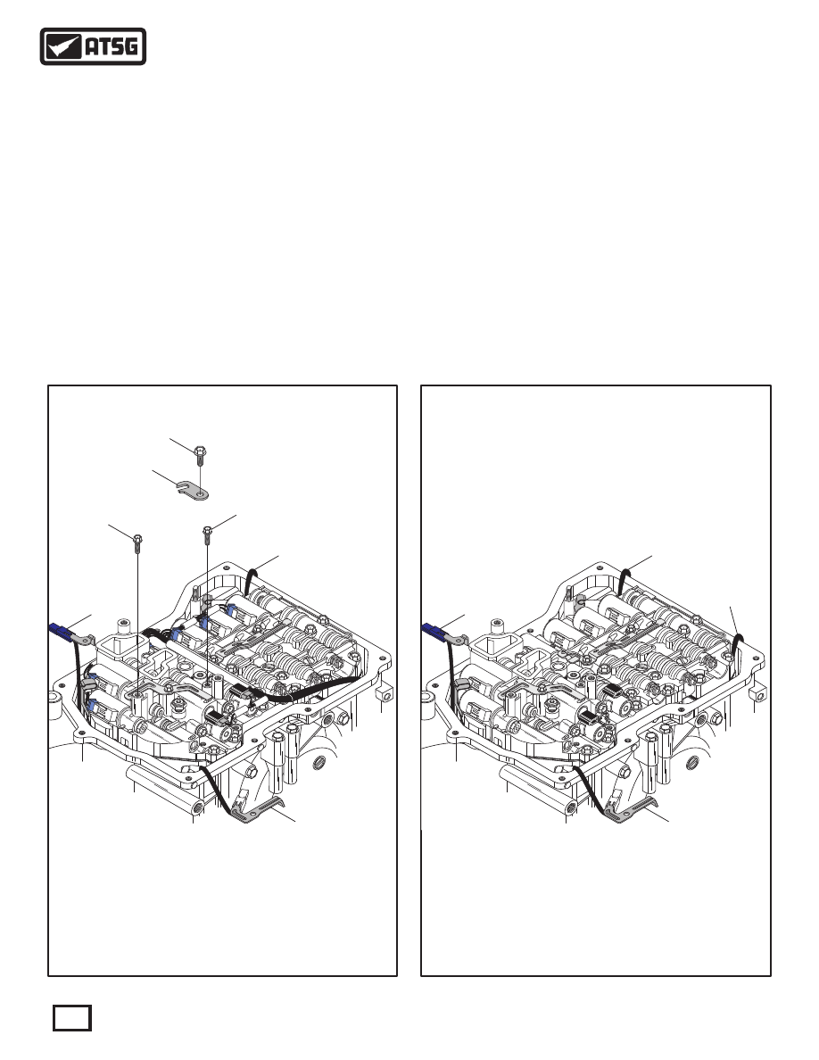
 14. Remove the bolts retaining the blue connector
       output speed sensor bracket and white connector
       input speed sensor brackets (See Figure 57).
 15. Remove the bolt retaining the TFT sensor and
       the retaining bracket, as shown in Figure 57.
 16. Remove the connectors from both speed sensors,
       both pressure switches (if used), as shown in
       Figure 57.
 17. Lay the sensor and switch harness from 8 way
       connector over the pan rail (See Figure 57).
 18. Lay the output speed sensor harness over the pan
       rail, as shown in Figure 57.
 19. Lay the input speed sensor harness over the pan
       rail, as shown in Figure 57.

 20. Remove all eight solenoid connectors from their
       respective solenoids  (See Figure 58).
       Caution: Now is another chance to log color of
       wires going to each and every solenoid before
       disconnecting them.
 21. Lay the solenoid wire harness from the 14 way
       connector over the pan rail  (See Figure 58).

Continued on Page 47

Figure 57

Figure 58

26

29

30

31

32

27

28

0

917

T1

7C

3

00

70

8

A

C

0

4

7

A3

0

70

C

C

B

01

37

1

5

Y3A

1

6

5B

X3

A0

70

5CB

3B

00

400

A

4

U3C

00

10

0

30

31

33

32

 26  OUTPUT SPEED SENSOR BRACKET BOLT  (11 MM LENGTH).
 27  TFT SENSOR RETAINING BRACKET.
 28  TFT SENSOR RETAINING BRACKET BOLT  (11 MM LENGTH).
 29  INPUT SPEED SENSOR BRACKET BOLT  (11 MM LENGTH).
 30  OUTPUT SPEED SENSOR HARNESS OVER PAN RAIL.
 31  INPUT SPEED SENSOR HARNESS OVER PAN RAIL.
 32  SENSOR AND SWITCH HARNESS OVER PAN RAIL.

 30  OUTPUT SPEED SENSOR HARNESS OVER PAN RAIL.
 31  INPUT SPEED SENSOR HARNESS OVER PAN RAIL.
 32  SENSOR AND SWITCH HARNESS OVER PAN RAIL.
 33  14 WAY SOLENOID HARNESS OVER PAN RAIL.

46

Technical Service Information

GAU6A06894

DCB6A0906

4

FBX6A0857

4

ABY6A0941

2

CCP6A09214

CCP6A09212

9170

T1

EO

Figure 59

Figure 60

 22. Remove only the 12 valve body to case bolts that
       are identified in Figure 59.
       Note: Valve body retaining bolts may vary in
       length from model to model.
 23. Remove the wire harness retaining brackets, as
       shown in Figure 60.
       Note: Wire harness retaining brackets will vary
       from model to model.
 24. Remove the valve body assembly, as shown in
       Figure 60.
 25. Set valve body assembly aside for component
       rebuild section.

Continued on Page 48

TRANSAXLE DISASSEMBLY (CONT'D)

C

C

C

C

A

A

B

B

B

B

C

C

 A = 16 mm Length
 B = 28 mm Length
 C = 21 mm Length

VALVE BODY TO CASE BOLTS

47

Technical Service Information

 30  OUTPUT SPEED SENSOR HARNESS OVER PAN RAIL.
 31  INPUT SPEED SENSOR HARNESS OVER PAN RAIL.
 32  SENSOR AND SWITCH HARNESS OVER PAN RAIL.
 33  14 WAY SOLENOID HARNESS OVER PAN RAIL.
 34  VALVE BODY  TO CASE BOLT  (16 MM LENGTH).
 35  VALVE BODY  TO CASE BOLT  (21 MM LENGTH).
 36  VALVE BODY  TO CASE BOLT  (28 MM LENGTH).
 37  WIRE HARNESS RETAINING BRACKET.
 38  WIRE HARNESS RETAINING BRACKET.

0

917

T1

C

7

3C

00

708

A

0

4

7C

A3

C0

70

5B

3

01

371

Y

A

5

X3

01

7

6

B

A

0

5

0

CB

3B00

4

0

A

4

U3C

00

100

34

35

35

35

35

35

35

36

36

36

36

38

37

34

Wire Harness

Bracket

Wire Harness

Bracket

30

31

33

32

Figure 62

Figure 61

 26. Remove the B1 accumulator piston and springs
       from transaxle case, as shown in Figure 61.
       Note: The number of B1 accumulator springs
       vary depending on year and model.  Best is to
       tag springs for identification.
 27. Remove the output speed sensor retaining bolt
       and output sensor, as shown in Figure 62.
       Note: This bolt has 8 mm head, 18 mm long.
 28. Remove the input speed sensor retaining bolt
       and the input sensor, as shown in Figure 62.
       Note: This bolt has 10 mm head, 21 mm long.

Continued on Page 49

TRANSAXLE DISASSEMBLY (CONT'D)

SOME

MODELS

ONLY

 30  OUTPUT SPEED SENSOR AND HARNESS ASSEMBLY.
 31  INPUT SPEED SENSOR AND HARNESS ASSEMBLY.
 32  SENSOR AND SWITCH HARNESS OVER PAN RAIL.
 33  14 WAY SOLENOID HARNESS OVER PAN RAIL.
 43  OUTPUT SPEED SENSOR RETAINING BOLT  (18 MM LENGTH).
 44  INPUT SPEED SENSOR RETAINING BOLT  (22 MM LENGTH).

 39  B1 ACCUMULATOR PISTON.
 40  B1 ACCUMULATOR PISTON INNER SPRING  (SOME MODELS).
 41  B1 ACCUMULATOR PISTON OUTER SPRING.
 42  B1 ACCUMULATOR PISTON SPRING.

30

31

33

32

39

40

41

42

43

44

39

Output Speed

Sensor Location

Input Speed

Sensor Location

48

Technical Service Information

 29. Remove the retaining bolt from 8-way connector
       and carefully remove the 8-way connector and
       wiring harness assembly, through the case bore,
       as shown in Figure 63.
       Note: Remove and discard the case connector
       "O" ring and temp sensor "O" ring.
 30. Remove retaining bolt from 14-way connector
       and carefully remove the 14-way connector and
       wiring harness assembly through the case bore,
       as shown in Figure 63.
       Note: Remove and discard the case connector
      "O" ring.

 32  8-WAY CASE CONNECTOR AND HARNESS ASSEMBLY.
 33  14-WAY CASE CONNECTOR AND HARNESS ASSEMBLY.
 45  CONNECTOR RETAINING BOLT (11 MM LENGTH FROM WASHER).
 46   8-WAY CONNECTOR TO CASE "O" RING SEAL.
 47  14-WAY CONNECTOR TO CASE "O" RING SEAL.
 48  TEMP SENSOR TO VALVE BODY "O" RING SEAL.

AU

FA

AU

FA

VW

  AG

V

  AG

W

0

0

GG

Z   

28

3

3

0

2

3

T0

1

8

C

2

6

09

G

0

H

 3

0 3

5

0

5

3

  0

7

44  2

-

 -

4

5

 1

0

1 -

 1

6

03

2

8

C

T0

21

O

Z

3

3

  0

H

00

5

09

G

10

04

45

45

46

47

48

33

32

Continued on Page 50

TRANSAXLE DISASSEMBLY (CONT'D)

Figure 63

49

Technical Service Information


Content   ..  102  103  104  105   ..