Volkswagen 01M Transmission. Manual - part 106
 

  Index      Volkswagen     Volkswagen 01M Transmission - service manual 2001 year


Search              


Content   ..  104  105  106  107   ..


Volkswagen 01M Transmission. Manual - part 106


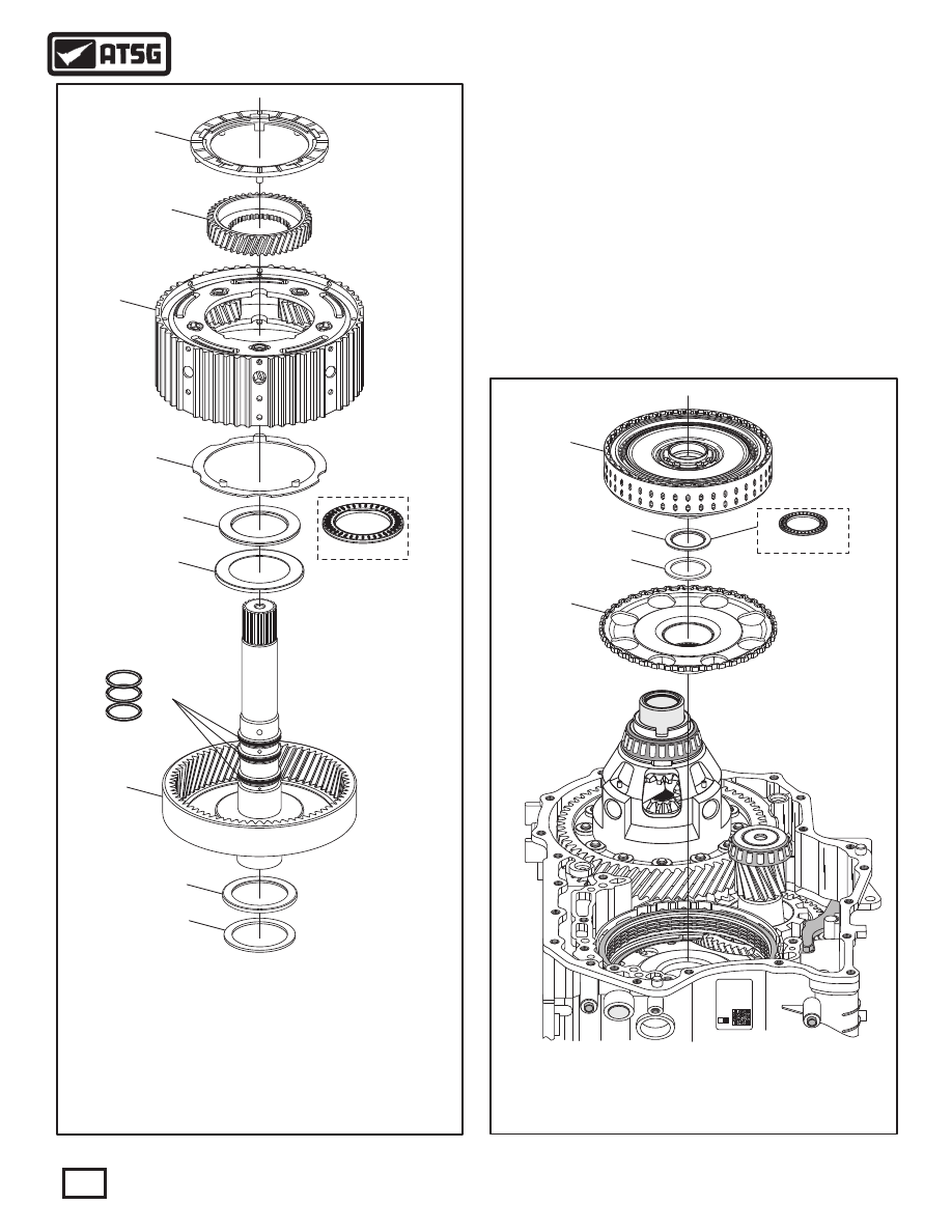
 111  NUMBER 2 THRUST WASHER.
 112  FRONT PLANETARY SUN GEAR.
 113  FRONT PLANETARY CARRIER ASSEMBLY.
 114  NUMBER 4 THRUST WASHER.
 115  INPUT SHAFT SEALING RINGS  (3 REQUIRED).
 116  NUMBER 3 THRUST BEARING.
 117  NUMBER 3 THRUST BEARING RACE.
 118  FRONT PLANETARY RING GEAR AND INPUT SHAFT ASSEMBLY.
 119  NUMBER 5 THRUST BEARING.
 120  NUMBER 5 THRUST BEARING RACE.

7

10

4051 - 1 - 1

03C2T02168

Z

0

300  035H

09G

1004

Figure 74

Figure 73

131

8

134

Continued on Page 55

 47. Seperate and inspect front planetary components,
       as shown in Figure 73.
 48. Remove K1 clutch housing assembly, as shown
       in Figure 74, and set aside for the component
       rebuild section.
 49. Remove the K3 clutch housing drive hub, as
       shown in Figure 74, along with the number 6
       thrust bearing and bearing race.

TRANSAXLE DISASSEMBLY (CONT'D)

120

119

118

115

117

116

114

113

112

111

133

132

REAR VIEW

REAR VIEW

 131  K1 CLUTCH HOUSING ASSEMBLY.
 132  NUMBER 6 THRUST BEARING.
 133  NUMBER 6 THRUST BEARING RACE.
 134  K3 CLUTCH HOUSING DRIVE HUB.

54

Technical Service Information

Continued on Page 56

 50. Remove the B1 clutch pack from the B1 clutch
       housing, as shown in Figure 75.
 51. Remove the B1 clutch housing retaining snap
       ring, as shown in Figure 76, and remove the
       B1 clutch housing.
       Note: This snap ring is identified by two small
       "turn-outs" at snap ring ends, as shown in
       Figure 76.

TRANSAXLE DISASSEMBLY (CONT'D)

10

7

4051 - 1 - 1

03C2T02168

Z

0

300  035H

09G

1004

7

4051 - 1 - 1

03C2T02168

Z

0

300  035H

09G

1004

Figure 76

Figure 75

424

425

426

427

422

421

423

 421  B1 CLUTCH "BELLVILLE" CUSHION SPRING.
 422  B1 CLUTCH BACKING PLATE.
 423  B1 CLUTCH FRICTION PLATES  (QTY MAY VARY).
 424  B1 CLUTCH STEEL PLATES  (QTY MAY VARY).
 425  B1 CLUTCH PRESSURE PLATE.

 426  B1 CLUTCH HOUSING RETAINING SNAP RING.
 427  B1 CLUTCH HOUSING.

55

Technical Service Information

56

Technical Service Information

Figure 77

Continued on Page 57

 52. Remove the 2 parking rod guide retaining bolts
       using a 10mm socket, as shown in Figure 78,
       and remove parking rod guide.
       Note: It is not necessary to remove the inside
       detent spring unless it is damaged.
 53. Remove the park pawl pivot pin case plug from
       rear of case, as shown in Figure 77.
 54  Remove and discard case plug "O" ring seal, as
       shown in Figure 77.

 55. Remove the park pawl pivot pin, using a small
       pocket magnet, through the case plug bore, as
       shown in Figure 77.

TRANSAXLE DISASSEMBLY (CONT'D)

AU

FA

AU

FA

W

V


G

 A

VW 

G

 A

GG

   280

30

3

Z


028

03C

1

2T

6
0

0

3

0 3

5

09

H

5

4


 - 

02

734

1

51


40

- 1

 -


03

C

T

16

8

2

02

O

Z

0

3

  0

5

0

3

H

9G

0

04

10

141

142

143

144

145

146

149

150

151

152

153

154

147

148

 148  PARK PAWL ANTI-RATTLE SPRING.
 149  PARK PAWL.
 150  PARK PAWL PIVOT PIN.
 151  PARK PAWL CASE PLUG "O" RING SEAL
 152  PARK PAWL CASE PLUG.
 153  INSIDE DETENT SPRING RETAINING BOLT.
 154  INSIDE DETENT SPRING.

 141  PARK ROD GUIDE RETAINING BOLT (14 MM LENGTH).
 142  PARK ROD GUIDE.
 143  PARK ROD GUIDE RETAINING BOLT (28 MM LENGTH).
 144  PARK PAWL RETURN SPRING SLEEVE.
 145  PARK PAWL RETURN SPRING.
 146  PARK ROD ROLLER AND PIN ASSEMBLY.
 147  PARK PAWL ANTI-RATTLE SPRING PIVOT PIN.

PARK LINKAGE EXPLODED VIEW

Figure 79

57

Technical Service Information

7

PARK ROD

GUIDE

INSIDE

DETENT

SPRING

7

4051 - 1 - 1

03C2T02168

Z

0

300  035H

09G

1004

146

147

148

149

TRANSAXLE DISASSEMBLY (CONT'D)

Continued on Page 58

 56. Remove park pawl anti-rattle spring and pivot
       pin, as shown in Figure 79.
 57. Remove the park rod roller and pin assembly, as
       shown in Figure 79.
 58. Remove the park pawl as shown in Figure 79.

Figure 78

 146  PARK ROD ROLLER AND PIN ASSEMBLY.
 147  PARK PAWL ANTI-RATTLE SPRING PIVOT PIN.
 148  PARK PAWL ANTI-RATTLE SPRING.
 149  PARK PAWL.


Content   ..  104  105  106  107   ..