Volkswagen 01M Transmission. Manual - part 107
 

  Index      Volkswagen     Volkswagen 01M Transmission - service manual 2001 year


Search              


Content   ..  105  106  107  108   ..


Volkswagen 01M Transmission. Manual - part 107


7

4051 - 1 - 1

03C2T02168

Z

0

300  035H

09G

1004

451

452

453

7

4051 - 1 - 1

03C2T02168

Z

0

300  035H

09G

1004

900

960

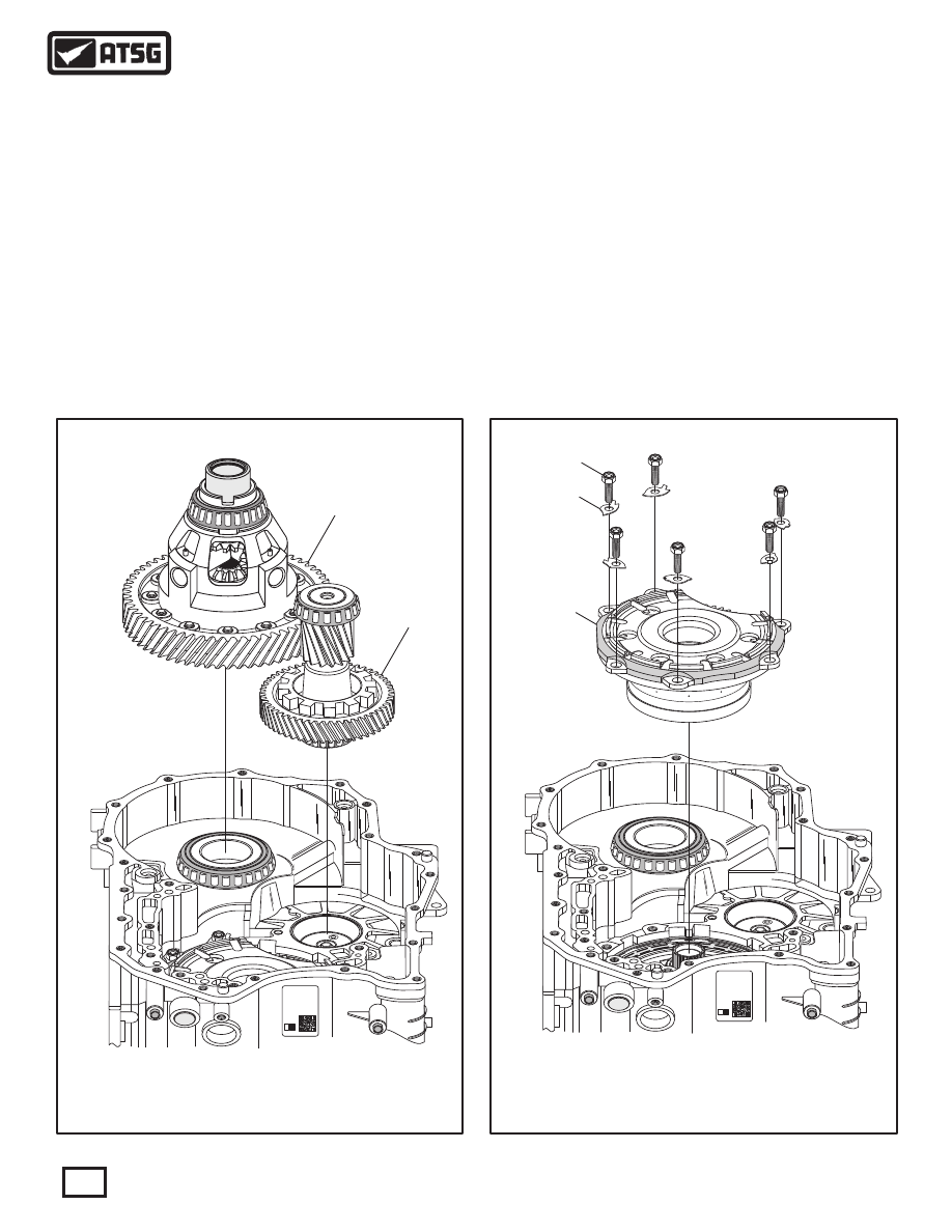
 900  FINAL DRIVE ASSEMBLY.
 960  TRANSFER DRIVEN GEAR AND PINION GEAR ASSEMBLY.

 451  CENTER SUPPORT RETAINING BOLTS  (6 REQUIRED).
 452  CENTER SUPPORT BOLT LOCKING TABS  (6 REQUIRED).
 453  CENTER SUPPORT ASSEMBLY.

TRANSAXLE DISASSEMBLY (CONT'D)

Continued on Page 59

 59. With the parking pawl removed, you can now
       remove the transfer driven gear and pinion gear
       assembly and the final drive assembly, as shown
       in Figure 80, and set aside for the component
       rebuild section.
 60. Remove the six center support retaining bolts, as
       shown in Figure 81, using a T-50 Torx bit or a
       14mm socket.
       Note: These six bolts are equipped with locking
       tab washers that must have the locking tab bent
       down before removing.

Figure 80

Figure 81

58

Technical Service Information

 61. Remove the center support assembly from the
       transaxle, as shown in Figure 81, and set the
       assembly aside for component rebuild.

 63. Carefully install the style of vice-grips that are
       shown in Figure 82, to the splines of the small
       sun gear.
 64. Use the vice-grips as a handle to remove the F1
       roller clutch and rear planetary gear-set as an
       assembly, as shown in Figure 82, and set aside
       for the component rebuild section.
 65. Remove the B2 clutch backing plate snap ring,
       as shown in Figure 83.
 66. Remove the complete B2 clutch pack from the
       transaxle case, as shown in Figure 83.

59

Technical Service Information

2

7

4051 - 1 - 1

03C2T02168

Z

0

300  035H

09G

1004

2

7

4051 - 1 - 1

03C2T02168

Z

0

300  035H

09G

1004

TRANSAXLE DISASSEMBLY (CONT'D)

 62. Remove the snap ring retaining F1 roller clutch,
       as shown in Figure 82.
       Note: This snap ring is .050" in thickness.

Continued on Page 60

Figure 82

Figure 83

 462  F1 ROLLER CLUTCH SNAP RING  (.050" THICKNESS).
 463  F1 ROLLER CLUTCH AND REAR GEAR SET ASSEMBLY.

 475  B2 CLUTCH BACKING PLATE SNAP RING.
 476  B2 CLUTCH COMPLETE ASSEMBLY.

462

462

475

476

7

4051 - 1 - 1

03C2T02168

Z

0

300  035H

09G

1004

 67. Remove the K2 clutch housing assembly along
       with the number 9 thrust bearing and races, as
       shown in Figure 84, and set aside for component
       rebuild section.
       Note: Number 9 front thrust bearing race may
       be stuck to the small sun gear in rear gear-set.
 68. Remove the number 11 thrust bearing and race,
       as shown in Figure 84.
       Note: Number 11 thrust bearing may be stuck
       to rear of K2 clutch housing.

7

4051 - 1 - 1

03C2T02168

Z

0

300  035H

09G

1004

TRANSAXLE DISASSEMBLY (CONT'D)

Continued on Page 61

Figure 85

Figure 84

60

Technical Service Information

471

472

473

511

480

481

512

513

 471  NUMBER 9 "FRONT" THRUST BEARING RACE.
 472  NUMBER 9 THRUST BEARING.
 473  NUMBER 9 "REAR" THRUST BEARING RACE.
 511  K2 CLUTCH HOUSING ASSEMBLY.
 512  NUMBER 11 THRUST BEARING.
 513  NUMBER 11 THRUST BEARING RACE.

 480  B2 CLUTCH RETURN SPRING SNAP RING  (.048" THICKNESS).
 481  B2 CLUTCH APPLY PISTON RETURN SPRING ASSEMBLY.

 69. Remove the B2 clutch return spring retaining
       snap ring, as shown in Figure 85.
 70. Remove the B2 clutch return spring assembly, as
       shown in Figure 85.

61

Technical Service Information

7

4051 - 1 - 1

03C2T02168

Z

0

300  035H

09G

1004

482

 482  B2 CLUTCH APPLY PISTON.

482

483

484

TRANSAXLE DISASSEMBLY (CONT'D)

 71. Apply compressed air to the B2 clutch passage
       in the case, as shown in Figure 86, to loosen the
       B2 clutch piston.
 72. Remove the B2 clutch piston from transaxle case
       as shown in Figure 87.
 73. Remove and discard the inner and outer "O" ring
       seals, as shown in Figure 88.
 74. This completes transaxle disassembly.

Figure 87

Figure 88

Figure 86

A

AD I 

U.S.

M

N

 482  B2 CLUTCH APPLY PISTON.
 483  B2 CLUTCH APPLY PISTON INNER "O" RING SEAL.
 484  B2 CLUTCH APPLY PISTON OUTER "O" RING SEAL.

B2 CASE PASSAGE


Content   ..  105  106  107  108   ..