Volkswagen 01M Transmission. Manual - part 109
 

  Index      Volkswagen     Volkswagen 01M Transmission - service manual 2001 year


Search              


Content   ..  107  108  109  110   ..


Volkswagen 01M Transmission. Manual - part 109


69

70

71

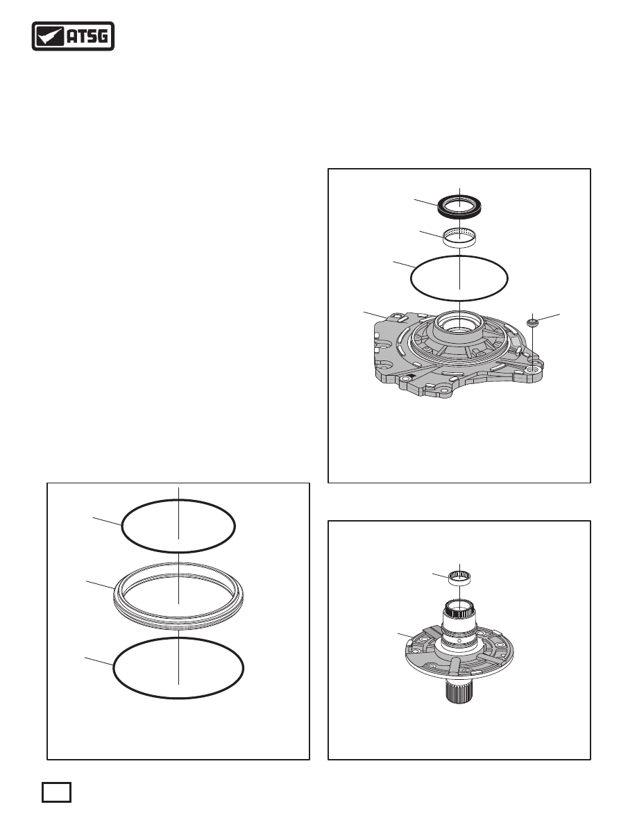
 69  B1 CLUTCH APPLY PISTON OUTER "O" RING SEAL.
 70  B1 CLUTCH APPLY PISTON.
 71  B1 CLUTCH APPLY PISTON INNER "O" RING SEAL.

32


6 1

C

A

58

59

60

61

62

 58  OIL PUMP CONVERTER HUB SEAL.
 59  OIL PUMP CONVERTER HUB BUSHING.
 60  OIL PUMP TO CONVERTER COVER "O" RING SEAL.
 61  OIL PUMP TO CONVERTER COVER SEAL ASSEMBLY.
 62  OIL PUMP BODY.

66

72

 66  OIL PUMP COVER AND STATOR SHAFT ASSEMBLY.
 72  OIL PUMP COVER CAGED NEEDLE BEARING.

COMPONENT REBUILD (CONT'D)

OIL PUMP ASSEMBLY (CONT'D)

   4. Install new "O" ring seals into the grooves on
       B1 clutch apply piston, as shown in Figure 96,
       and lube with small amount of Trans-Jel®.
   5. Install new pump body to converter housing
       "O" ring seal, as shown in Figure 97, and lube
       with small amount of Trans-Jel®.
   6. Install new pump body bushing as necessary
       using the proper driver  (See Figure 97).
   7. Install new converter hub seal into pump body,
       as shown in Figure 97, using proper driver.
   8. Install new pump body to converter cover seal
       (61), as shown in Figure 97, and retain with a
       small amount of Trans-Jel®.
       Note: This step can wait until you have the
       oil pump installed on transaxle, if you wish.
   9. Inspect the caged needle bearing in the pump
       cover, as shown in Figure 98.
       Note: This bearing is not serviced and pump
       cover will require replacement if damaged.

Figure 96

Figure 98

Figure 97

Continued on Page 67

66

Technical Service Information

INNER GEAR TO FACE

.0008" - .0015"

.0008" - .002"

.003" - .005"

COMPONENT

Oil Pump Specifications

SPECIFICATION

OUTER GEAR TO FACE

OUTER GEAR TO BODY

62

63

63

64

65

"DOTS"

FACING UP

 62  OIL PUMP BODY.
 63  OIL PUMP HOLLOW ALIGNMENT DOWELS  (2 REQUIRED).
 64  OIL PUMP OUTER GEAR, GEROTOR STYLE.
 65  OIL PUMP INNER GEAR, GEROTOR STYLE.

62

66

67

 62  OIL PUMP BODY.
 66  OIL PUMP COVER AND STATOR SHAFT ASSEMBLY.
 67  PUMP COVER RETAINING BOLTS & WASHERS (8 REQUIRED).

67

Technical Service Information

Continued on Page 68

COMPONENT REBUILD (CONT'D)

OIL PUMP ASSEMBLY (CONT'D)

 10. Install the oil pump body alignment dowels, as
       shown in Figure 99, if removed.
 11. Install the oil pump inner and outer gears into
       the pump body, as shown in Figure 99, with
       the "dots" facing up.
 12. Lubricate the gears with small amount proper
       transaxle fluid.
 13. Measure the gear to face clearance on both the
       inner and outer gears using a feeler gage or a
       depth micrometer, as shown in Figure 100.
       Note: Oil Pump Specifications are also shown
       in Figure 100.
 14. Install the oil pump cover into the oil pump
       body, as shown in Figure 101, and install the
       eight bolts and washers.

Figure 99

Figure 101

Figure 100

S

t

t

ar

t

re

9

8

0

-O

Sn

ap

n

TORQUE BOLTS TO

11 N·M  (97 IN.LB.)

 70  COMPLETED B1 CLUTCH APPLY PISTON.

70

73

68

 68  OIL PUMP COVER, BUTT-CUT, SEAL RINGS  (2 REQUIRED).
 73  NUMBER 1 THRUST WASHER.

COMPLETED OIL PUMP ASSEMBLY

68

Technical Service Information

Component Rebuild

Continued on Page 69

COMPONENT REBUILD (CONT'D)

OIL PUMP ASSEMBLY (CONT'D)

 15. Torque the eight oil pump cover to pump body
       bolts down to 11 N·m (97 in.lb.), as shown in
       Figure 102, using a criss-cross pattern.
 16. Lubricate the "O" ring seal surfaces in the oil
       pump cover with small amount of Trans-Jel®.
 17. Install the B1 clutch apply piston into the oil
       pump cover, as shown in Figure 103.
 18. Install the number 1 thrust washer onto back
       of pump cover, as shown in Figure 104, and
       retain with small amount of Trans-Jel®.
       Note: This thrust washer is included in the
       Trans-Tec® gasket pack.

Figure 102

Figure 103

Figure 105

Figure 104

 19. Install two new sealing rings into grooves of
       the pump cover, as shown in Figure 104, and
       ensure butt ends meet.
 20. Lubricate seal rings with transaxle fluid and set
       completed oil pump aside for final assembly, as
       shown in Figure 105.

69

Technical Service Information

6

100

101

102

103

104

105

106

109

108

107

110

 100  K3 CLUTCH HOUSING ASSEMBLY.
 101  K3 CLUTCH PISTON OUTER "O" RING SEAL.
 102  K3 CLUTCH APPLY PISTON.
 103  K3 CLUTCH PISTON INNER "O" RING SEAL.
 104  K3 CLUTCH PISTON RETURN SPRING ASSEMBLY.
 105  K3 CLUTCH BALANCE PISTON.

 106  K3 CLUTCH BALANCE PISTON SNAP RING.
 107  K3 CLUTCH STEEL PLATES.
 108  K3 CLUTCH FRICTION PLATES.
 109  K3 CLUTCH BACKING PLATE.
 110  K3 CLUTCH BACKING PLATE SNAP RING  (.064" THICK).

K3 CLUTCH EXPLODED VIEW

COMPONENT REBUILD (CONT'D)

K3 CLUTCH HOUSING ASSEMBLY

Figure 106

   1. Disassemble the K3 clutch housing assembly
       using Figure 106 as a guide.
   2. Clean all K3 clutch housing parts thoroughly
       and dry with compressed air.
   3. Inspect all K3 clutch housing parts thoroughly
       for wear and/or damage, replace as necessary.

WARNING: At time of this printing, there are not 
any  new  "hard  parts"  available  from  the 
manufacturer for this unit. The only source will be 
used aftermarket suppliers.

Continued on Page 70


Content   ..  107  108  109  110   ..